
TM 1-4920-433-13&P
FIELD MAINTENANCE
PNEUDRAULIC SHOP
MAINTENANCE INSTRUCTIONS FOR ECU CABLE ASSEMBLY
INITIAL SETUP:
Tools and Special Tools
Personnel Required
CMF 15 Series (1)
General Mechanics Tool Kit
(WP 0062 00, Table 2, Item 104 )
Equipment Condition
Functional
INSPECTION OF INSTALLED ITEMS
ECU SUPPORT CABLE ASSEMBLY
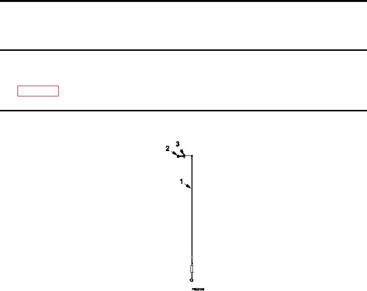
Figure 1.
ECU Support Cable Assembly.
Inspect
1.
Inspect ECU support cable assembly (Figure 1, Item 1) for loose countersunk machine screw (Figure 1, Item
2).
2.
Tighten countersunk machine screw (Figure 1, Item 2), if necessary.
REMOVAL
ECU SUPPORT CABLE ASSEMBLY
1.
Remove one countersunk machine screw (Figure 1, Item 2) and one washer (Figure 1, Item 3).
2.
Remove ECU support cable assembly (Figure 1, Item 1).
INSTALLATION
ECU SUPPORT CABLE ASSEMBLY
Position ECU cable assembly (Figure 1, Item 1) and install one countersunk machine screw (Figure 1, Item 2)
and one washer (Figure 1, Item 3).
END OF WORK PACKAGE
0055 00-1/2 blank

