
TM 1-4920-435-13&P
0047 00
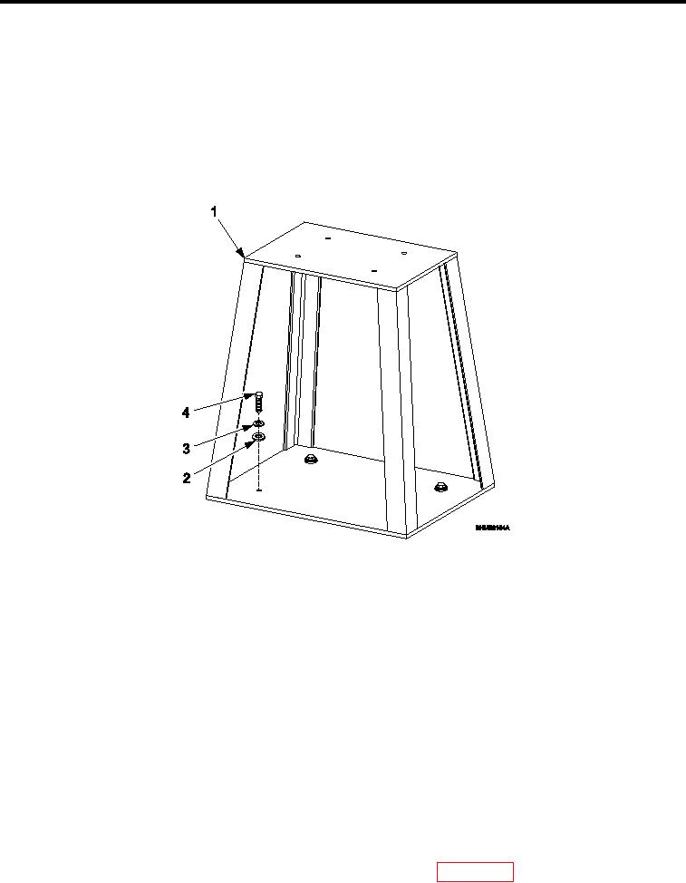
INSTALLATION
THROATLESS SHEARING MACHINE
1.
Align bolt holes of throatless shearing machine (Figure 1, Item 1) with mounting holes on anvil/throatless
shearing machine stand assembly (Figure 1, Item 2).
2.
Install four bolts (Figure 1, Item 7) four upper lat washers (Figure 1, Item 6), four lower lat washers (Figure
1, Item 5), four lock washers (Figure 1, Item 4), and four nuts (Figure 1, Item 3) from anvil/throatless shearing
machine stand (Figure 1, Item 2).
INSPECTION OF INSTALLED ITEMS
ANVIL/THROATLESS SHEAR STAND ASSEMBLY
Figure 2.
Anvil/Shear Stand Assembly and Hardware.
1.
Inspect anvil/shear stand assembly (Figure 2) for damage. Replace as necessary.
2.
Inspect anvil/shear stand assembly hardware (Figure 2, Item 2 through 4) for rust, cracks and rounded
heads. Replace as necessary.
REMOVAL
ANVIL/THROATLESS SHEAR STAND ASSEMBLY
1.
Remove throatless shearing machine IAW Throatless Shearing Machine, REMOVAL.
2.
Remove four bolts (Figure 2, Item 4), four lock washers (Figure 2, Item 3), and four lat washers (Figure 2,
Item 2).
REPAIR OR REPLACEMENT
ANVIL/THROATLESS SHEAR STAND ASSEMBLY
1.
If anvil/shear stand assembly (Figure 2, Item 1) can be repaired by welding, weld damaged area IAW TM
1-1500-204-23. Repair must not interfere with form, it, or function of anvil/shear stand assembly (Figure 2,
Item 1).
2.
Paint repaired anvil/shear stand assembly (Figure 2, Item 1) IAW WP 0068 00, Figure 11.
0047 00-3

