
TM 1-4920-436-13&P
0011 00
POSITIONING ECU (B) FOR OPERATIONAL MODE - CONTINUED
NOTE
Mounting hardware is supplied with ECU.
6.
Mount ECU (B) (Figure 10, Item 1) to ECU fold-down panel (Figure 10, Item 2).
7.
Remove four ring bolts from ECU transport location and store in shelter BII box.
8.
Remove four setscrews (WP 0065 00, Figure 2, Item 18 or 19) from shelter BII box and install into empty loor
inserts.
CONNECTING POWER TO ECUS
NOTE
There are several ECU conigurations compatible for this shop set. Refer to the applicable ECU
Owner s Manual for operating, grounding, and maintenance instructions.
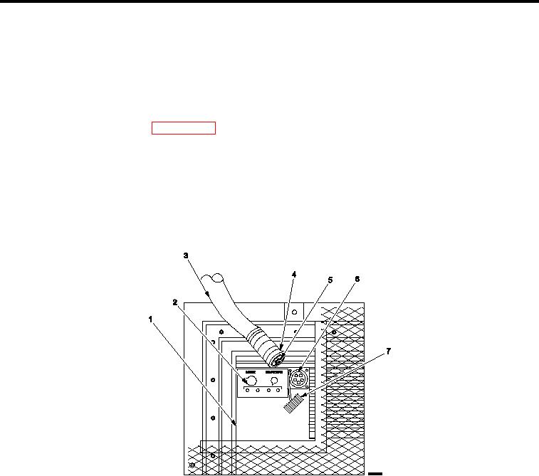
Figure 11.
Connecting Power to ECU s.
1.
Inspect installation of ECU (A) (Figure 11, Item 1) and power cable (Figure 11, Item 3).
2.
Position MODE switch (Figure 11, Item 2) to OFF position.
3.
Remove protective dust cap (Figure 11, Item 7) from power input receptacle (Figure 11, Item 6).
4.
Push end of connector (Figure 11, Item 5) into power input receptacle (Figure 11, Item 6) until seated.
5.
Screw connector lock ring (Figure 11, Item 4) on power input receptacle (Figure 11, Item 6).
6.
Repeat Steps 1 through 5 for ECU (B).
END OF WORK PACKAGE
0011 00-9/10 blank

