
TM 1-4920-440-13&P
0055 00
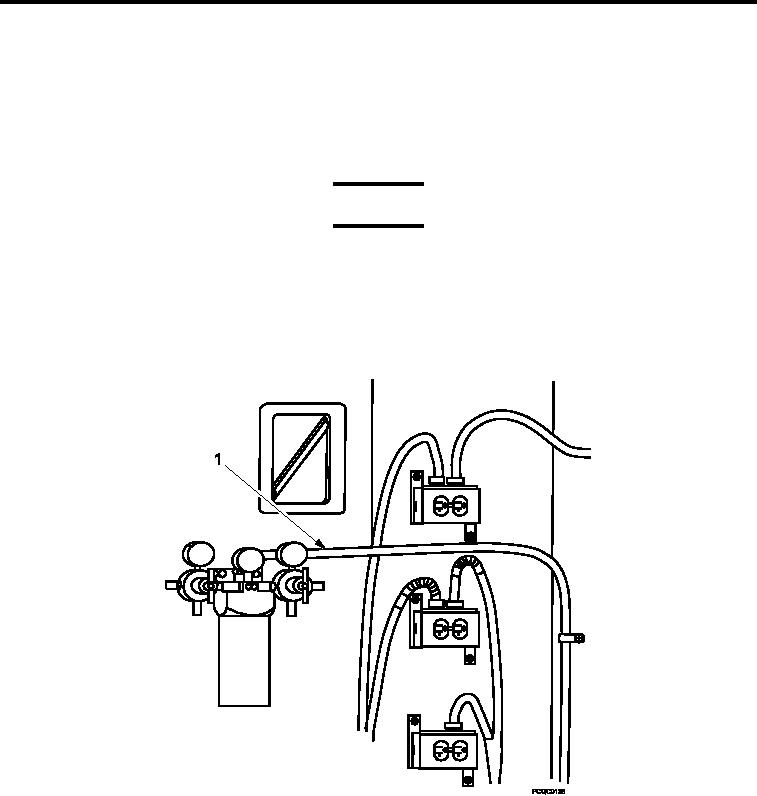
INSTALLATION
Oil/Water Separator
1.
Position oil/water separator (Figure 1, Item 1) over wall inserts.
2.
Install two bolts (Figure 1, Item 4), two lock washers (Figure 1, Item 3), and two lat washers (Figure 1, Item
2).
Torque bolts (Figure 1, Item 4) 160-190 in. lbs.
3.
WARNING
Ensure compressed air supply is disconnected before attempting any work on oil/water sep-
arator. Do not direct compressed air near eyes or directly against skin. Wear goggles; high
pressure air against eyes can cause BLINDNESS.
INSPECTION OF INSTALLED ITEMS
Non-metallic Hose and Fittings
Figure 2.
Hose and Fittings.
1.
Inspect non-metallic hose (Figure 2, Item 1) for visible damage.
2.
Replace non-metallic hose (Figure 2, Item 1) if damage is detected.
0055 00-3

