
0013
TM 1-4920-924-13&P
AVIATION SHOP EQUIPMENT CONTACT MAINTENANCE (AV SECM) SYSTEM MAINTENANCE
INSTRUCTIONS FOR WORKBENCH ASSEMBLY - (CONTINUED)
1.
Position spring sheet nuts (Figure 6, Item 1) in groove (Figure 6, Item 2) of corner casting (Figure 6, Item 4)
with raised portion of spring sheet nuts (Figure 6, Item 1) facing end of corner casting (Figure 6, Item 4).
2.
Install aluminum rail (Figure 6, Item 3) onto corner casting (Figure 6, Item 4) ensuring spring sheet nuts
(Figure 6, Item 1) stays positioned in groove (Figure 6, Item 2) of corner casting (Figure 6, Item 4).
3.
Ensure end of aluminum rail (Figure 6, Item 3) is seated lush against corner casting (Figure 6, Item 4).
Repeat Steps 13 for installing all aluminum rails (Figure 6, Item 3) to corner castings (Figure 6, Item 4).
4.
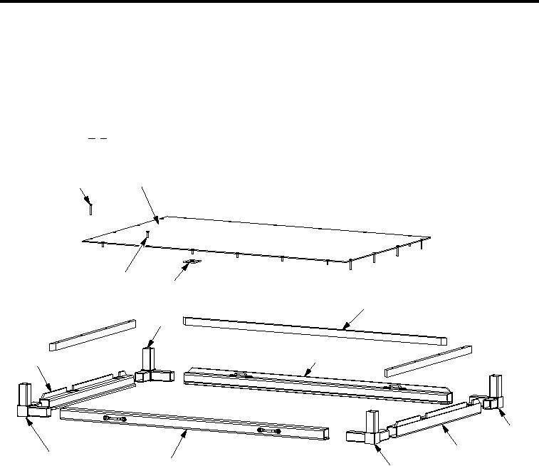
Third Shelf
2
1
13
12
3
11
4
10
5
6
9
8
7
SECM0054
Figure 7.
Third Shelf
1.
Install two corner castings (Figure 7, Item 9 and 11) into aluminum rail (Figure 7, Item 10).
2.
Install two corner castings (Figure 7, Item 9 and 11) into aluminum rails (Figure 7, Item 4 and 8).
3.
Install two corner castings (Figure 7, Item 5 and 7) into aluminum rail (Figure 7, Item 6).
4.
Install two corner castings (Figure 7, Item 5 and 7) into aluminum rails (Figure 7, Item 4 and 8).
5.
Install three shims (Figure 7, Item 3) and one support plate (Figure 7, Item 2).
6.
If aluminum rails (Figure 7, Item 4, 6 or 10) were replaced then follow procedures in Installation of Helical.
7.
On aluminum rails (Figure 7, Item 4, 6 or 10) install fourteen 10-32 X 1.38 inch countersunk screws
(Figure 7, Item 1).
8.
On aluminum rail (Figure 7, Item 8) install six 10-32 X 0.63 inch countersunk screws (Figure 7, Item 13) and
six speed nuts (Figure 7, Item 12) securing support plate (Figure 7, Item 2).
001310

