
TM 10-5411-236-13&P
0013 00
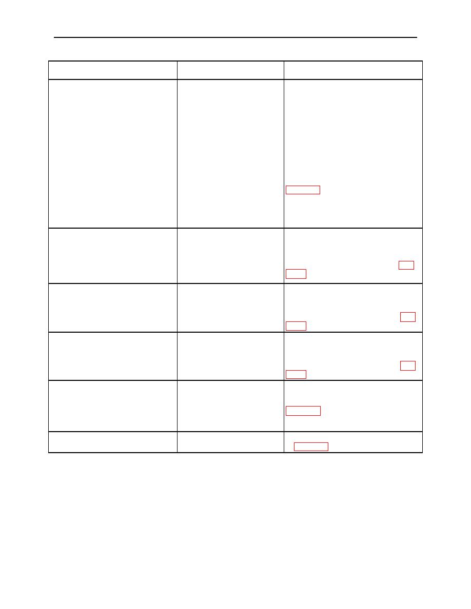
Table 1. Operator Troubleshooting (cont'd)
Malfunction
Test or inspection
Corrective action required
Visually inspect to ensure
ASLMS is connected to
PDISE and breakers are set
to the on position. Visually
Connect to PDISE and position the
inspect to ensure the two
breakers to the on position. Connect
150-foot power cables are
the two 150-foot power cables to the
connected to the ASLMS.
FPU-12. Connect the DC power
Visually inspect to ensure
40. Light Does Not Operate.
cable between the FPU-12 and FPU-
the 9-foot DC power cable
8 containers. Coordinate with the
that joins the DC electrical
generator operator to obtain a
from the FPU-12 to the
connection to the PDISE. (Refer to
FPU-8 is connected. Check
to ensure the PDISE is
connected to the power
generator and the generator
is operational.
Visually inspect to ensure
Extend or retract the pole until the
EPC frame poles are in their
black rings are aligned and re-pin.
41. EPC Frame Poles Do Not Fit
deployed position. Check to
Obtain proper pole number for the
Properly.
ensure that the correct pole
position being erected. (Refer to WP
is being installed to its
0009 00.)
proper position.
Check to ensure that the
Reposition EPC cover to align the
black arrow on the EPC
arrow on top off and at the end of the
42. EPC Cover Does Not Fit
cover is draped over and at
FPU-8 with the arrow hanging over
Properly.
the center of the FPU-8
and pointed downward. (Refer to WP
container.
0009 00.)
Check to ensure that the
Reposition EPC cover to align the
black arrow on the EPC
arrow on top off and at the end of the
43. EPC Doors Misaligned.
cover is draped over and at
FPU-8 with the arrow hanging over
the center of the FPU-8
and pointed downward. (Refer to WP
container.
0009 00.)
Visually inspect to ensure
that orientation of tensioning
44. Tensioning Straps Do Not Fit
Re-orientate and connect. (Refer to
straps is proper for mating
Properly.
WP 0009 00.)
ends of EPC cover straps to
connect.
45. Floor Adapter Plate Does Not
Inspect for debris under the
Clean as required and install. (Refer
Fit Smoothly to Floor.
floor adapter plate.
to WP 0006 00, 0034 00.)
0013 00-6

