
TM 10-5411-236-13&P
0053 00
6. Remove the four 1/4" 20 x 1" distribution box securing screws (3).
7. Pull distribution box (1) down and remove.
8. Attach new distribution box (4) with the four 1/4" 20 x 1" securing screws (3).
9. Feed wires and conduit through holes located in the top of the distribution box (1).
10. Install and tighten conduit nuts (2).
11. Remove all receptacles (10) from the new distribution box (1) by removing the four #5 40 x -inch
fillister head screws, (9) hex head nuts (8) and lock washers (7) using a flat head screw driver and
5/16-inch open end wrench.
12. Pull wires through the three openings in the bottom of the of the distribution box being careful to
ensure that the marked wires are oriented as follows: From left to right L1(4) , DC (5) , L2 (6).
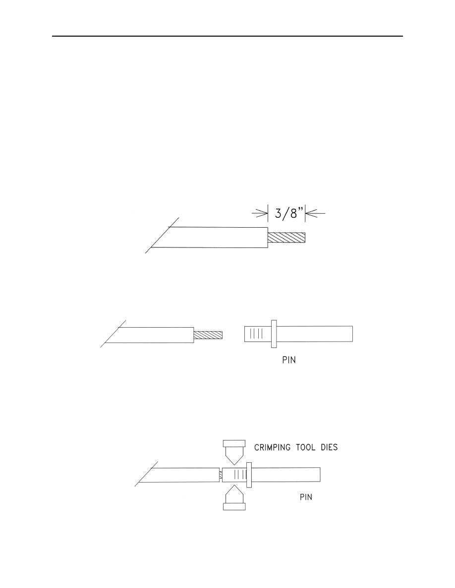
13. Strip insulation back 3/8-inch (10mm) on all wires using a stripper tool.
14. Insert stripped wire into female pin connector.
15. Using a type AF8 crimping tool with wire size setting 12 and depth setting yellow (12) at the end of
the pin, crimp until the ratcheting action is released
0053 00-3

