(2)
Remove cartridge from cylinder.
(a)
Type I and Type II (Air) Purifier
Cylinder Thoroughly clean the inside
of cylinder with a-lint free cloth using
hot water and detergent solution per
Federal Specification P-D-220 Allow to
air dry.
(b)
Type II (Oxygen) Purifier Cylinder.
Closely
inspect
inside
of
oxygen
purifier
cylinder
Make
certain
no
foreign substance is present Oxygen
clean as necessary
(3)
Examine o-rings in the cylinder caps and
replace if damaged (See Figure 7-2 and 7-
3)
(4)
Place fresh type MA-2 Cartridges In the
Type I and Type II Air Purifier Cylinder, and
m the Type II Oxygen Purifier Cylinder
Screw the cap assembly snugly in place Do
NOT over tighten
(5)
Using a strap wrench, screw cylinder caps
back onto the cylinders Apply enough force
to caps to pierce the cartridges with the
built-in
piercing
blades
have
entered
cartridges Screw cap down firmly against
cylinder Do not overtighten
NOTE
1-ach time cartridges are Installed, record
time and date on applicable forms
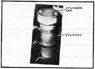
Figure 5-1. Purification Cylinder
b.
WELDED
FRAME
ASSEMBLY
(See
19,Figure 7-1) If it Is necessary to repair a cracked weld
on the frame proceed as follows
Do NOT use welding equipment near
compressed gas cylinders or compressed
gas systems
Make sure all air or oxygen pressure has
been removed from the tubing and flex hose
system before any disassembly of the
Service Units take place
(1)
Remove all air or oxygen pressure from
Service Unit System (see Section IV)
before disassembly begins
(2)
Remove compressed gas cylinders from
Service Units. (See Section VI, Repair
Instructions )
(3)
As required, remove control panel from
Service Units. (See Section VI, Repair
Instructions )
5-3.
CHASSIS: Trailer, 3/4-Ton, 2-Wheel, M116AI -
See TM 9-2330-202-14P for Inspection and preservative
maintenance and lubrication instructions
5-4.
TROUBLESHOOTING (See Table 5-2) This
table will aid and guide maintenance personnel by
indicating some of the potential problem areas while
operating the service units.
5-2