
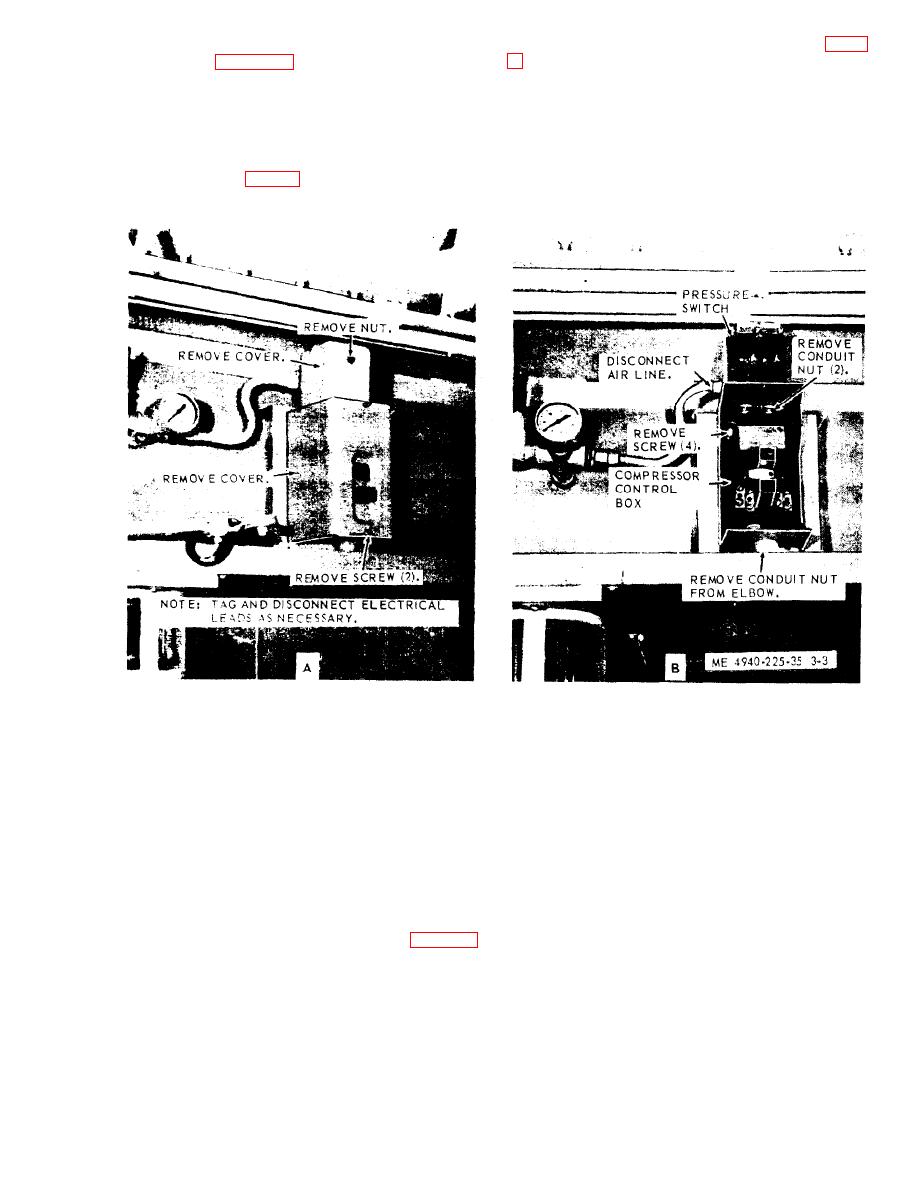
(2) Disconnect air line to pressure gage (fig. 3-
e. Reassembly. Reassemble the drive motor as
illustrated in figure 3-2.
(3) Tag and disconnect electrical leads from
f. Instal[ation. Install the motor (TM 5-4940-
225-12).
pressure switch.
(4) Remove two conduit locknuts and remove
3-3 Pressure Switch
pressure switch from the starter box.
a. Removal.
b. Installation. Install in reverse order of
(1) Remove screw
and remove
cover on
a above.
pressure switch (fig. 3-3).
c. Adjustment. Refer to TM 5-4940-225-12 for
adjustment.
Figure 3-3. Air compressor pressure and starter control box, removal and installation.
(3) Remove conduit nut from elbow.
3-4. Air Compressor Starter Control Box
(4) Remove four screws and remove starter
a. Removal.
control box from bracket.
(1) Remove pressure switch (para 3-3).
b. Installation. Install in reverse order of
(2) Tag and disconnect electrical leads (fig. 3-
a above.
3).
Section II. DYNAMOTOR-WELDER
dynamotor-welder. The exciter, its commutator and
3-5. General
brushes, and the alternator, with its sliprings and
On-equipment electrical test procedures (para 3-9)
brushes, are located at the drive end.
determine the necessity and extent of electrical
Warning: Before performing any main-
repair of the dynamotor-welder. When making on-
tenance procedures on the electrical system,
equipment tests, refer to the practical wiring
see that all external power is disconnected from
diagram in figure 1 and figure 2. Note that the
the shop set and stop the truck engine.
direct current welder generator, commutator, and
brushes are located at the non-drive end of the
3-7

