
TM 55-4920-213-15
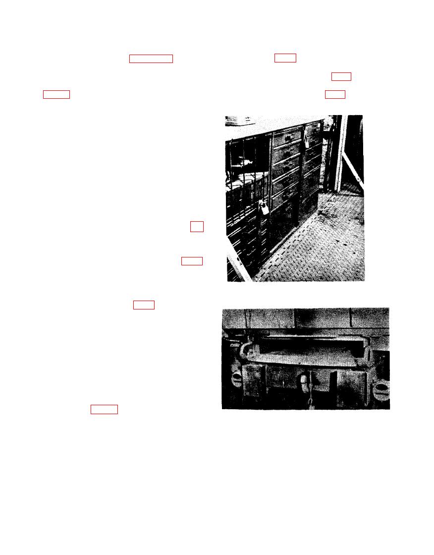
c. Install security locking bars on cabinets
are contained in the manuals issued for the in-
with drawers (fig. 6).
dividual items. Refer to appendix I for listing
of Technical Manuals. It is-essential that the
d. Secure tools or equipment too large for
operator understand these instructions.
bin storage in space provided (fig. 7).
b. Perform after-operation daily services
e. Secure equipment in open bins with web
straps or special fastenings (fig. 6).
(par. 31-34).
f. Store cable or hose in locations provided.
14. Operating Details
a. General. These instructions provide t
operator with necessary details for operation
the equipment in the shop set.
b. Electrical System.
(1) Ascertain that circuit breakers in ele
trical panel, are in the ON positi
for circuits to be used.
(2) Insert plugs of equipment cords int
receptacles provided.
c. Pneumatic System.
(1) Start the air compressor in accordanc
with the TM for the compressor (app
I).
(2) Allow sufficient time for buildup o
source pressure in the tank, and drain
the oil and water separator (fig. 5)
Note. The correct source pressure is 75 to
150 psi.
(3) Close drain when water or oil cease
to drain from separator.
fastenings; typical installation.
(4) Adjust controls (fig. 5), to obtain an
operating pressure of 75 psi.
(5) Check connections for leaks, security
of fittings, and condition.
(6,) Insert adapters, attached to pneumatic
equipment hose, into receptacles pro-
vided.
Note. When an external power source is
utilized for pneumatic power, omit (1) above.
15. Movement of Equipment
a. Perform "at halt" and "after operation"
daily service (table I).
b. Store all tools and equipment.
Section IV. OPERATION OF ONE UNIT IN CONJUNCTION
WITH ANOTHER ACCESSORY OR AUXILIARY
rate technical manuals of the auxiliary equip-
ment.
Instructions
Maintenance and operating instructions for
Connections are provided for auxiliary pneu-
the auxiliary equipment to be used in conjunc-
matic and electrical hookups. The location,
tion with this shop set are listed in the sepa-

