
16
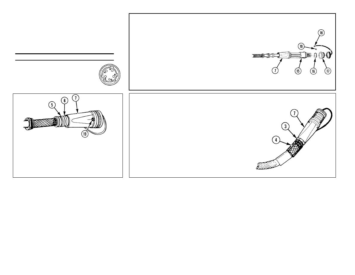
PIN SOCKET (15).
Table 3-8. Wire Positioning on Connector
Slide into rear connector housing
(7).
NOTE
Use the following information
17
PREFORMED
PACKING
(16).
to
obtain
correct
wire
Install.
polarity.
18
FORWARD
CONNECTOR
Wire color
Designation on socket
HOUSING (17).Install.
Black
A
19
EYELET OF DUST COVER (18)
Red
B
AND SCREW (19). Assemble.
Blue or Orange
C
White
N
Green G
22
GRIP (4). Push together.
CAUTION
Gland nut has left-hand
threads and should be
tightened by turning in the
opposite direction from that
used to tighten standard
right-hand threaded nuts.
20
THREE SCREWS (19). Install.
21
SPACER (6) AND GLAND (5). Slide
23
GLAND NUT (3).
into position at end of rear connector
housing (7).
a. Slide toward rear connector housing (7).
3-289

