Home
Download PDF
Order CD-ROM
Order in Print
Figure 13. Components to be Mounted, Unit 2, M105A2, Left Side Elevation.
Figure 15. Electrical Components to be Mounted, Unit 1, M35A2, Floor Plan.
TB-9-4910-745-30 (NSN 4910-00-754-0705) Installation In One M35A2 Cargo Truck and One M105A2 Cargo Trailer Manual
Page Navigation
23
24
25
26
27
28
29
30
31
32
33
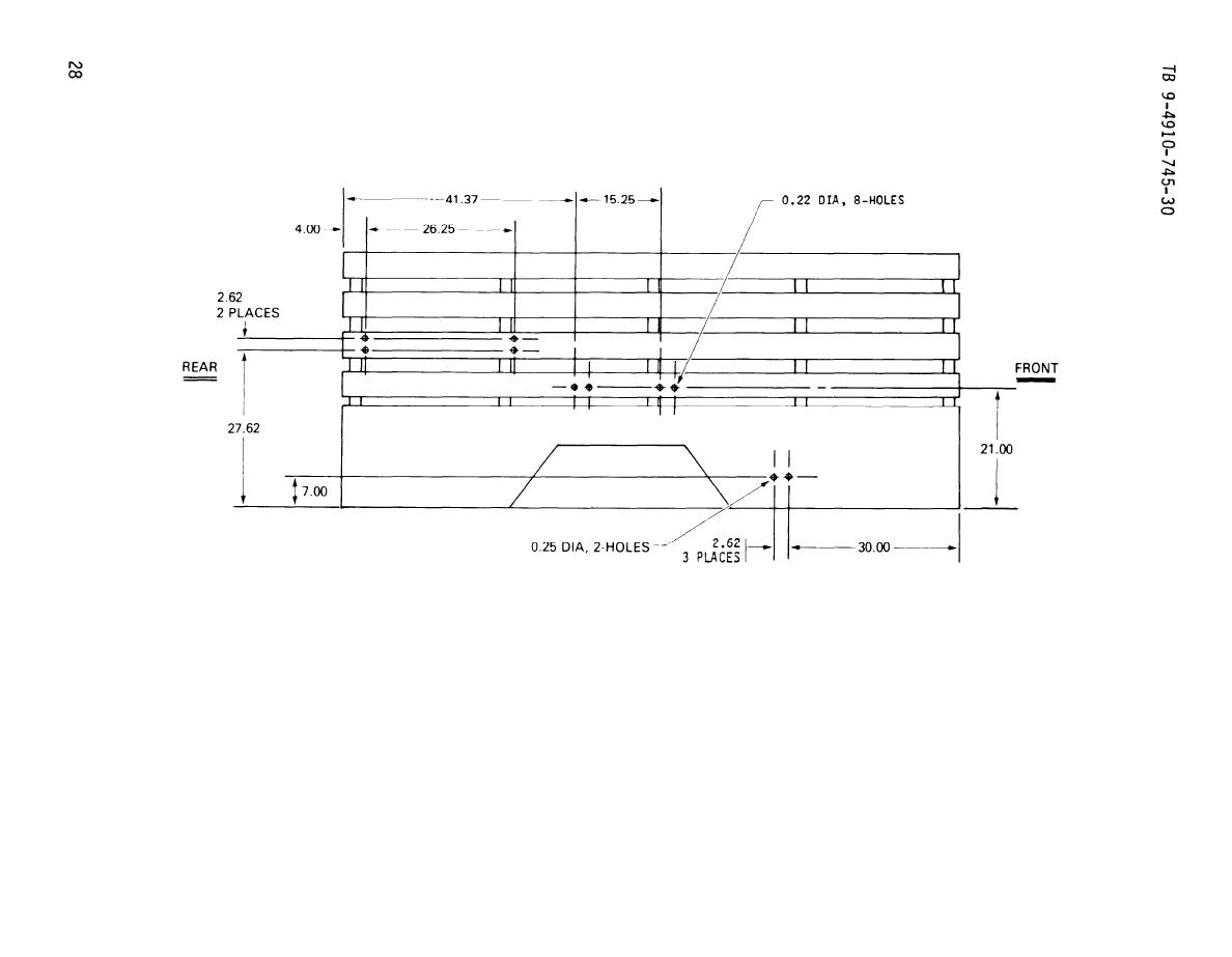
Figure
14.
Hole
Dimensions
for Blind Rivet
Nuts
and
Strap
Loops,
Unit 2,
M105A2,
Left
Side
Elevation.