
TM 1-4920-436-13&P
0002 00
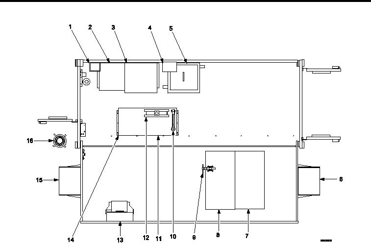
LOCATION AND DESCRIPTION OF MAJOR COMPONENTS CONTINUED
Item No. and Name
Item No. and Name
1. First Aid Kit and Bracket Assembly
9. Machinist Vise
10. 10 Ton Hydraulic Press
2. 4 Drawer Cabinet (A) and Shelf Cabinet (A)
3. 6 Drawer Cabinet (B)
11. 4 Drawer Cabinet (F)
12. 10 Ton Hydraulic Press
4. Ultrasonic Cleaner Generator
5. Ultrasonic Cleaner
13. Eyewash Station Assembly
6. ECU (B)
14. 4 Drawer Cabinet (E)
7. Shelf Cabinet (D)
15. ECU (A)
8. Shelf Cabinet (C)
16. Cable Reel Assembly and 100 amp Power
Cable Assembly
Figure 7.
Operational Mode Component View (1035258).
0002 00-7