
TM 1-4920-438-13&P
0002 00
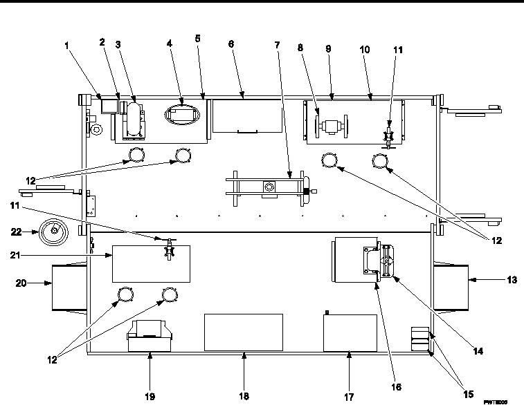
LOCATION AND DESCRIPTION OF MAJOR COMPONENTS CONTINUED
Item No. and Name
Item No. and Name
1. First Aid Kit and Bracket Assembly
12. Stools (6)
2. 4 Drawer Cabinet (A)
13. ECU (B)
3. Upright Drilling Machine
14. Open Throat Press
4. Dry Ice Maker
15. Case Sets
5. 4 Drawer Cabinet (B)
16. 4 Drawer Cabinet (F)
6. Degreaser
17. Mechanical Refrigerator Freezer
7. 25 Ton Arbor Press
18. Shelf Cabinet (E)
8. 1/2 HP 7in. Grinder
19. Eyewash Station Assembly
9. 4 Drawer Cabinet (C)
20. ECU (A)
10. 4 Drawer Cabinet (D)
21. Shelf Cabinet (G)
11. Machinist s Vise
22. 60 amp Power Cable Assembly
Figure 5.
Operational Mode Component View (SC4920-97-CLA65).
0002 00-5