
TM 1-4920-441-13&P
0011 00
POSITIONING ECU (B) FOR OPERATIONAL MODE - CONTINUED
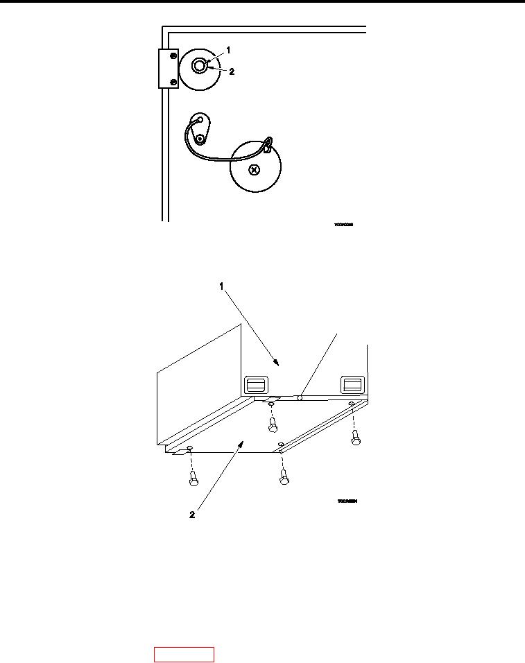
Figure 9.
Aligning Bolt Holes of ECU (B) with ECU Fold-down Panel.
5.
Align bolt holes (Figure 9, Item 1) in base of ECU with ECU fold-down panel holes (Figure 9, Item 2).
Figure 10.
Securing ECU (B) to ECU Fold-down Panel.
NOTE
Mounting hardware is supplied with ECU.
6.
Mount ECU (B) (Figure 10, Item 1) to ECU fold-down panel (Figure 10, Item 2).
7.
Remove four ring bolts from ECU transport location and store in shelter BII box.
8.
Remove four setscrews (WP 0064 00, Figure 2, Item 18 and 19) from shelter BII box and install into empty
loor inserts.
0011 00-7