f.
With air compressor unit operating pull ENGINE
THROTTLE CONTROL to the full out position and lock in
place.
g.
Push
ENGINE
THROTTLE
CONTROL
completely in to stop.
h.
If engine does not stop, loosen wire stop (13,
Figure 8-30) and adjust throttle lever until engine stops.
Without disturbing setting of throttle lever, tighten wire
stop (13).
i.
Repeat steps a through e. Pull engine
THROTTLE CONTROL to the full out position and lock
by turning handle in clockwise direction. The engine
should operate at 2150 i 50 rpm (2150 + 50 r/min).
WARNING
Make certain all control valves on control panel are
closed.
j.
Engage clutch by pushing CLUTCH operating rod
towards panel. Place COMPRESSOR UNLOADER
switch to LOAD position to pressurize receiver.
k.
Observe Service Pressure gauge (4, Figure 4-2) indi-
cation. With air compressor unit operating under normal
conditions, the compressor unit should unload at a maxi-
mum pressure of 3400 psig (23, 426 kPa). The air
compressor unit should load at a minimum pressure of
3100 psig (21, 359 kPa). If air compressor loads or
unloads
at
an
in-correct
pressure,
refer
to
TROUBLESHOOTING (Section V).
l.
Open the SERVICE HOSE BLEED valve, MECH-
ANICAL FILTER DRAIN valve and DEHYDRATOR
BLEED VALVE. Observe the COMPRESSOR OUTPUT
and SERVICE PRESSURE pressure gauges.
m. Place the COMPRESSOR UNLOADER SWITCH
(16, Figure 4-2) to the UNLOAD position.
n.
Disengage clutch by pulling CLUTCH operating rod
away from control panel. Push ENGINE THROTTLE
CONTROL in to the idle position.
o.
Allow engine to run without a load at idle speed for
approximately five (5) minutes.
p.
Push ENGINE THROTTLE CONTROL completely
in. Turn MASTER SWITCH 450 ccw.
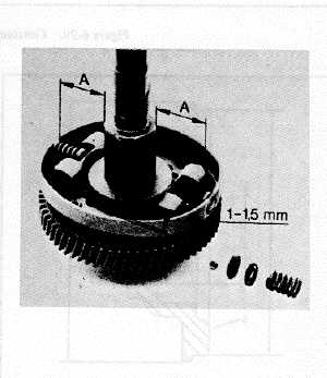
Figure 6-28. Spring Plate to Camshaft Adjustment.
6-73


