
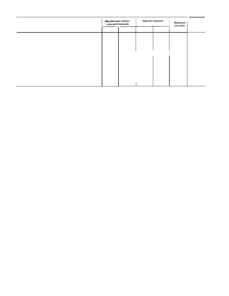
Table 1-1. Air Compressor Repair and Replacement Standard.~--Continued.
Maximum
allowable
Component
clearance
Maximum
wear
Minimum
Minimum
Maximum
Connecting Rods and Bearings:
L. P. Connecting rod:
.0015
.0009
().8750
().8755
.0006
0.0001
Pin bearing id. . . . . . . . . . . . . . . . . . .
.0002
.0013
1.3753
1.3763
Rod bearing id . . . . . . . . . . . . . . . . .
Rod bearing length . . . . . . . . . . . . . . . . . 1.495
0.020
1.500
0.010
0.001 TIR (Total Indirector Reading)
Rod twist . . . . . . . . . . . . . . . . . . . . . . .
0.0003TIR
Rod bend . . . . . . . . . . . . . . . . . . . . . . .
H. P. Connecting rod:
00009
001 5
.0006
0.8750
0.0001
0.8755
Pin bearing id . . . . . . . . . . . . .
.0013
Rod bearing id . . . . . . . . . . . . . . . . . 1.3753
.0002
1.3763
0.020
1 . 5 0 0 0.010
Rod bearing length . . . . . . . . . . 1 . 4 9 5
0.001 TIR
Rod twist . . . . . . . . . . . . . . . . . . .
0.003 TIR
Rod bend . . . . . . . . . . . . . . . . . . . . . .
d. Wiring Diagrams. For 24-volt and 110-volt
schematic wiring diagrams, refer to TM 5-4940 -
225-12
Figure 1-1. Schematic wiring diagram (dynamotor-welder).
(Located in back of mannual)
Figure l-2. Schematic wiring diagram (dynamotor-welder).
(Located in back of manual)
Cylinder bead bolts. . . . . . . . . . 24 to 26 ft-lb
e. Compressor Torque Data.
Main bearing plate bolts 24 to 26 ft-lb
Connecting rod bolts . . . . .14 to 16 ft-lb (foot-pounds)
1-4
