Home
Download PDF
Order CD-ROM
Order in Print
Figure 2. Components to be mounted, unit 1, 280, floor plan. - TB-9-4940-319-300020
Figure 4. Components to be mounted, left side elevation, unit 1, 280.
TB-9-4940-319-30 Welding Shop (NSN 4940-00-209-6240) Installation In One 280 Maintenance Shelter (NSN 4940-00-919-8409) and One ISO-2-1 Manual
Page Navigation
12
13
14
15
16
17
18
19
20
21
22
TB
9-4940-319-30
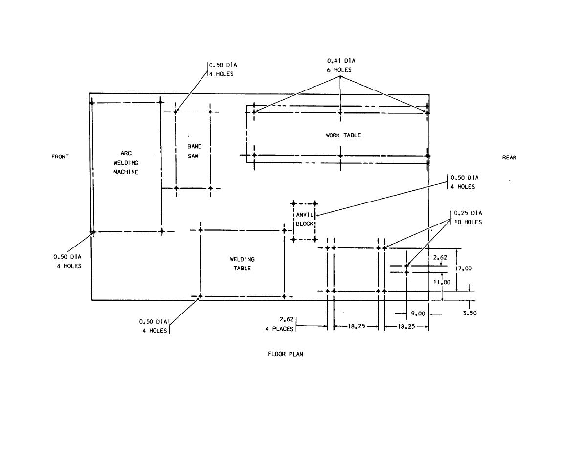
Figure
3.
Dimensions
for
floor-mounted
blind
rivet
nuts
and
equipment
mounting
holes,
unit
1,
280,
floor
plan.
17