
TM 1-4920-433-13&P
0006 00
CONNECTING MAIN POWER CABLE - CONTINUED
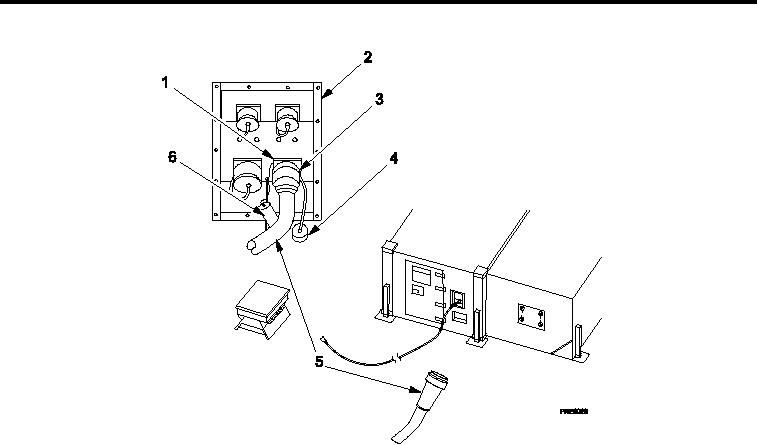
Figure 6.
Connecting Main Power Cable to Shelter.
7.
Remove protective dust cap (Figure 6, Item 6) from "J1" receptacle (Figure 6, Item 1) at power entry panel
(Figure 6, Item 2).
8.
Remove protective dust cap (Figure 6, Item 4) from female power connector (Figure 6, Item 5).
9.
Insert female power connector (Figure 6, Item 1) into "J1" receptacle (Figure 6, Item 1) and secure with lock
ring (Figure 6, Item 3).
0006 00-5