
TM 1-4920-433-13&P
FIELD MAINTENANCE
PNEUDRAULIC SHOP
MAINTENANCE INSTRUCTIONS FOR GROUND ROD
INITIAL SETUP:
Personnel Required
Tools and Special Tools
CMF 15 Series (1)
Electrical Repairers Tool Kit
Equipment Condition
(WP 0062 00, Table 2, Item 103 )
Functional
Multimeter (WP 0062 00, Table 2, Item 106 )
WARNING
HIGH VOLTAGE exists in electrical system of shop. All electrical inspections, repairs, or
replacements will be performed with power OFF and only by a qualiied electrician. Serious
shock hazards exist which could result in INJURY OR EVEN DEATH to personnel.
INSPECTION OF INSTALLED ITEMS
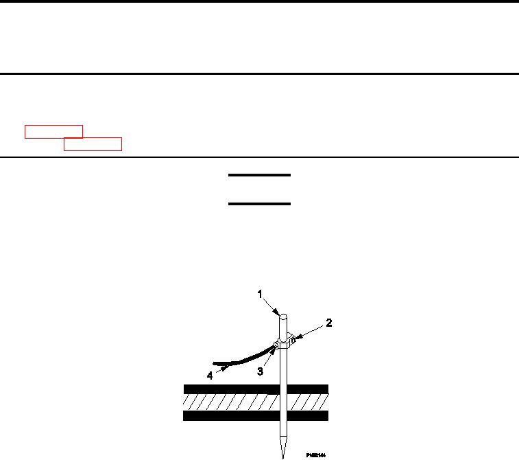
Figure 1.
Inspect Ground Rod.
1.
Move main circuit breaker to OFF position.
2.
Ensure ground rod (Figure 1, Item 1) is irmly driven into ground.
3.
Ensure electrical clamp (Figure 1, Item 2) and screw (Figure 1, Item 3) are securely fastened.
4.
Ensure there is no sign of oxidation around clamp (Figure 1, Item 2) or screw (Figure 1, Item 3).
5.
Ensure that ground cable (Figure 1, Item 4) is not frayed or broken.
6.
Move main circuit breaker to ON position.
0057 00-1