
0005 00
TM 1-4920-436-13&P
INITIAL LEVELING
WARNING
Four personnel are required to perform all of the following procedures. Failure to observe
warning could result in SERIOUS INJURY to personnel.
1.
Remove level from shelter Basic Issue Items (BII) box.
2.
Level both cargo and personnel end (WP 0002 00, Figure 1) from side to side, and middle of shelter from end
to end by adjusting leveling support jack assemblies accordingly.
SHELTER EXPANSION
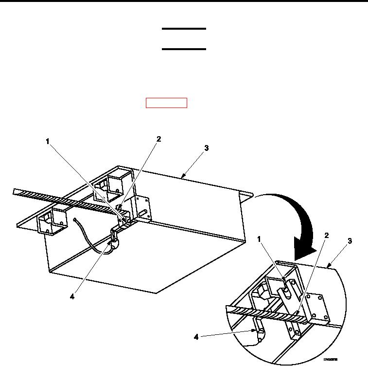
Figure 3.
Load Balancer Slide Stops, Upper Positions.
1.
Remove lockout pins (Figure 3, Item 4) from lower position on both load balancers (Figure 3, Item 3).
2.
Open slide stops (Figure 3, Item 1) against support cables (Figure 3, Item 2 ) on both load balancers.
3.
Install lockout pins (Figure 3, Item 4) in upper position on both load balancers.
0005 00-4