
TM 1-4920-436-13&P
0006 00
CONNECTING MAIN POWER CABLE - CONTINUED
CAUTION
Ensure power cable assembly is not twisted, kinked, or placed over sharp rocks or projections.
Where possible, cable should not be routed through any deep ground depressions where water
may accumulate.
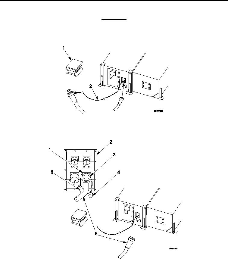
Figure 5.
Extending Main Power Cable.
6.
Extend power cable assembly (Figure 5, Item 2) between shop and PDB (Figure 5, Item 1).
Figure 6.
Connecting Main Power Cable to Shelter.
7.
Remove protective dust cap (Figure 6, Item 6) from "J1" receptacle (Figure 6, Item 1) at power entry panel
(Figure 6, Item 2).
8.
Remove protective dust cap (Figure 6, Item 4) from female power connector (Figure 6, Item 5).
0006 00-5