
0019 00
TM 1-4920-436-13&P
DISCONNECTING POWER FROM ECUS - CONTINUED
5.
Install protective dust cap (Figure 1, Item 7) on power input receptacle (Figure 1, Item 6).
6.
Repeat Steps 1 through 5 for ECU (A).
POSITIONING ECU (B) FOR TRANSPORT MODE
1.
Remove four setscrews from ECU (B) transport location loor inserts and store in shelter BII box.
2.
Remove two cargo straps (Figure 3, Item 3) from secure storage location and four ring bolts (Figure 3, Item
4) from shelter BII box.
3.
Install four ring bolts (Figure 3, Item 4) into loor inserts at transport location.
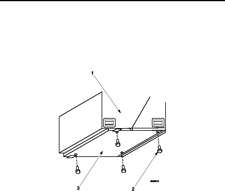
Figure 2.
Removing ECU (B) Hardware from ECU Fold-down Panel.
4.
Remove mounting hardware (Figure 2, Item 2) securing ECU (B) (Figure 2, Item 1) to ECU fold-down panel
(Figure 2, Item 3).
5.
Store mounting hardware (Figure 2, Item 2) in shelter BII box.
0019 00-2