
TM 1-4920-436-13&P
OPERATOR INSTRUCTIONS
ENGINE SHOP
POSITIONING ECUS FOR TRANSPORT MODE
INITIAL SETUP:
References
Tools and Special Tools
General Mechanics Tool Kit
Applicable ECU Owner s Manual
(WP 0060 00, Table 2, Item 104 )
Equipment Condition
Personnel Required
Functional
CMF 15 Series (4)
DISCONNECTING POWER FROM ECUS
NOTE
There are several ECU conigurations compatible for this shop set. Refer to the applicable ECU
owner s manual for shutdown and storage instructions.
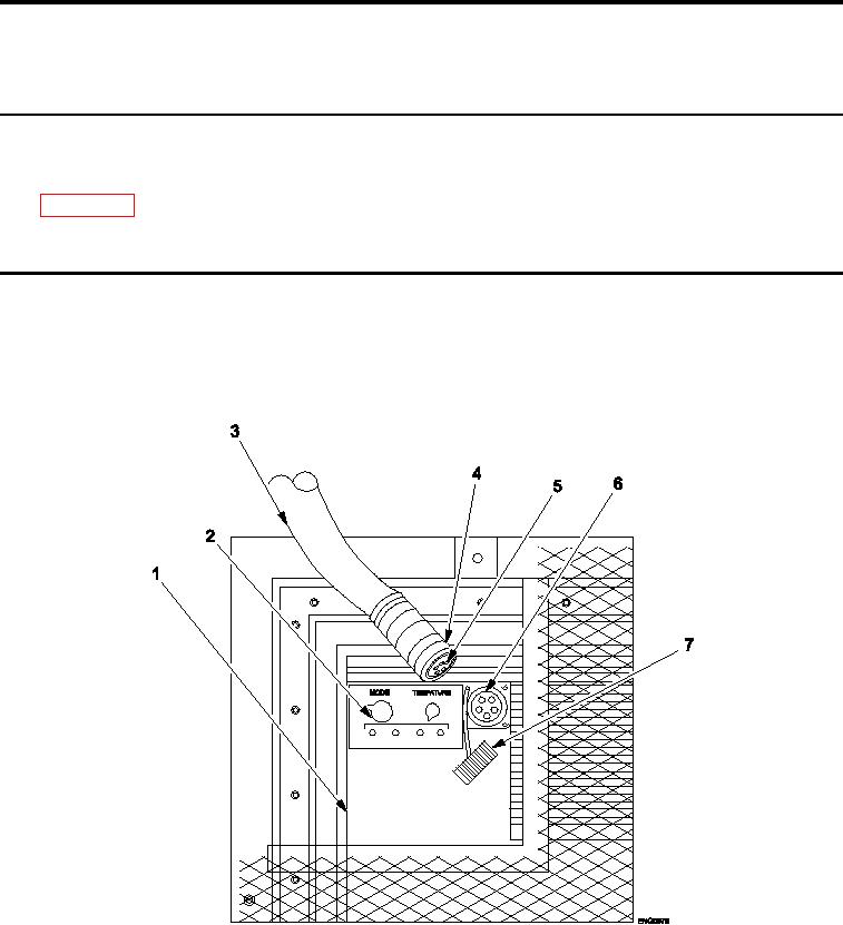
Figure 1.
Disconnecting Power from ECUs.
1.
Set MODE switch (Figure 1, Item 2) on ECU (B) (Figure 1, Item 1) to OFF position.
2.
Unscrew connector lock ring (Figure 1, Item 4) from power input receptacle (Figure 1, Item 6).
3.
Pull end of connector (Figure 1, Item 5) from power input receptacle (Figure 1, Item 6).
4.
Store power cable (Figure 1, Item 3) in secure storage location.
0019 00-1