
0008 00
TM 1-4920-438-13&P
OPENING ECU FOLD-DOWN PANELS - CONTINUED
4.
Lower fold-down panel (Figure 5, Item 1) using d-rings, to limit of support cables (Figure 5, Item 2) on end
wall from outside shelter.
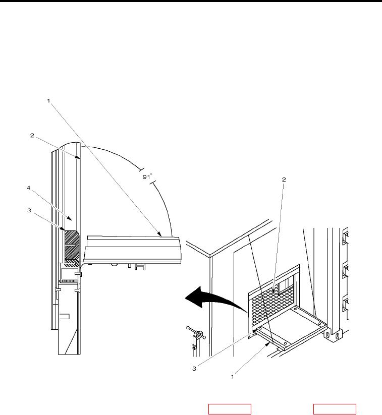
NOTE
ECU fold-down panel must be at an angle of approximately 91 degrees in order for water to
properly drain.
Figure 6.
Installing T-Seal.
5.
Remove T-seal (Figure 6, Item 3) from shelter BII box (WP 0002 00, Figure 2, Item 8 or WP 0002 00, Figure
3, Item 8).
NOTE
T-seal must be positioned with metal strip against ECU security screen.
6.
Insert T-seal (Figure 6, Item 3) into gap (Figure 6, Item 4) located between ECU fold-down panel (Figure 6,
Item 1) and ECU security screen (Figure 6, Item 2).
0008 00-6