
0012
TM 1-4920-924-13&P
AVIATION SHOP EQUIPMENT CONTACT MAINTENANCE (AV SECM) SYSTEM MAINTENANCE
INSTRUCTIONS FOR ROADSIDE RACK ASSEMBLY - (CONTINUED)
1.
On left ifth shelf (Figure 18, Item 2) of roadside rack assembly (Figure 18, Item 1), measure 2.00 inches
from front edge of left ifth shelf (Figure 18, Item 2) for stencil placement for TAARTS (1025209-01)
(Figure 18, Item 4).
2.
On left ifth shelf (Figure 18, Item 2) of SECM roadside rack assembly (Figure 18, Item 1), measure 1.25
inches from right side of third shelf (Figure 18, Item 2) for stencil placement for 160 LBS MAX LOAD
(1025209-35) (Figure 18, Item 4).
3.
On right ifth shelf (Figure 18, Item 2) of roadside rack assembly (Figure 18, Item 1), measure 2.00 inches
from front edge of right ifth shelf (Figure 18, Item 2) for stencil placement for UMARK (1025209-07)
(Figure 18, Item 5).
4.
On right ifth shelf (Figure 18, Item 2) of SECM roadside rack assembly (Figure 18, Item 1), measure
1.25 inches from right side of third shelf (Figure 18, Item 2) for stencil placement for 160 LBS MAX LOAD
(1025209-35) (Figure 18, Item 3).
END OF TASK
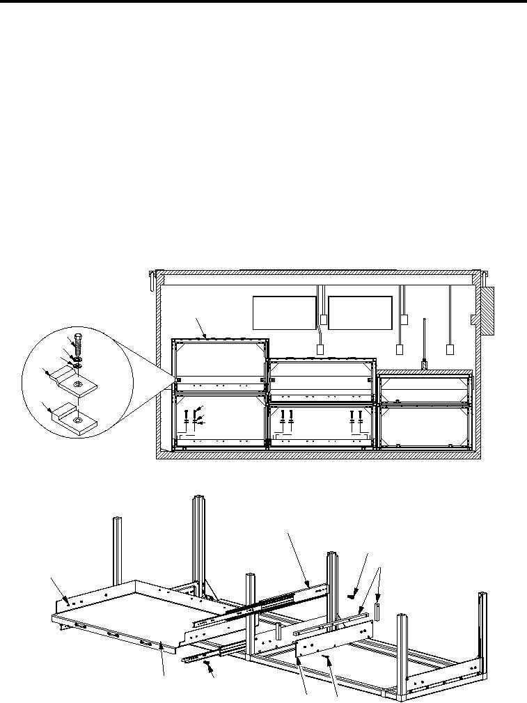
INSTALLATION
1
5
3
4
6
7
2
3
4
SECM0041
Figure 19.
Installation (Sheet 1 of 2).
8
9
10
15
14
13
SECM0042
12
11
Figure 19.
Installation (Sheet 2 of 2).
001228