
0013
TM 1-4920-924-13&P
AVIATION SHOP EQUIPMENT CONTACT MAINTENANCE (AV SECM) SYSTEM MAINTENANCE
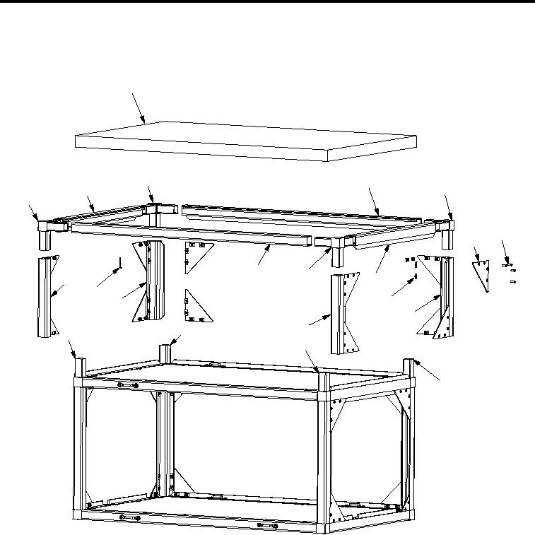
INSTRUCTIONS FOR WORKBENCH ASSEMBLY - (CONTINUED)
First Shelf
1
21
2
3
20
19
4
5
13
12
9
18
16
8
15
7
11
14
17
10
6
SECM0057
Figure 10.
1.
Install four aluminum rails (Figure 3, Item 7, 11, 15 and 18) onto four corner castings (Figure 3, Item 6, 10,
14 and 17).
2.
Install two corner castings (Figure 3, Item 19 and 21) into aluminum rail (Figure 3, Item 20).
3.
Install two corner castings (Figure 3, Item 3 and 12) into aluminum rail (Figure 3, Item 9).
4.
Install two corner castings (Figure 3, Item 19 and 21) into aluminum rails (Figure 3, Item 2 and 13).
5.
Install two corner castings (Figure 3, Item 3 and 12) into aluminum rails (Figure 3, Item 2 and 13).
6.
Install four corner castings (Figure 3, Item 3, 12, 19 and 21) into four aluminum rails (Figure 3, Item 7, 11,
15 and 18).
7.
Install forty-eight 10-32 X 0.63 inch countersunk screws (Figure 3, Item 4), forty-eight speed nuts
(Figure 3, Item 8), and twelve large gussets (Figure 3, Item 5).
001314