
0013
TM 1-4920-924-13&P
AVIATION SHOP EQUIPMENT CONTACT MAINTENANCE (AV SECM) SYSTEM MAINTENANCE
INSTRUCTIONS FOR WORKBENCH ASSEMBLY - (CONTINUED)
9. Install three shims (Figure 8, Item 4) and one support plate (Figure 8, Item 3).
10. On aluminum rails (Figure 8, Item 5, 21 and 23) install fourteen 10-32 X 1.38 inch screws (Figure 8, Item
1) and fourteen speed nuts (Figure 8, Item 10).
11. On aluminum rail (Figure 8, Item 15) install six 10-32 X 0.63 inch countersunk screws (Figure 8, Item 2) and
six speed nuts (Figure 8, Item 10) securing support plate (Figure 8, Item 3).
12. If support plate (Figure 8, Item 3) has been replaced, proceed to Steps 1319.
NOTE
The following steps are only necessary if the SECM workbench assembly second shelf support
plate has been replaced. The following steps are required on a replacement SECM workbench
assembly second shelf support plate to allow for installation of power inverter.
13. On top side of support plate (Figure 8, Item 1), measure from right side of support plate towards left 1.75
inches and from front of support plate (Figure 8, Item 1) towards back 7.00 inches and mark measurement
(Figure 8, Item 5).
1
1
2
3
7
4
6
5
SECM0056
Figure 9. Second Shelf Support Plate
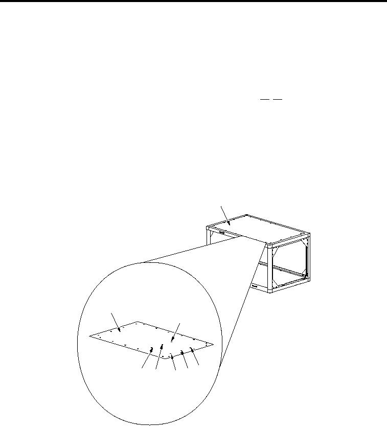
14. On top side of support plate (Figure 9, Item 1), measure from right side of support plate towards left 1.75
inches and from front of support plate (Figure 9, Item 1) towards back 12.50 inches and mark measurement
(Figure 9, Item 4).
15. On top side of support plate (Figure 9, Item 1), measure from right side of support plate towards left 1.75
inches and from front of support plate (Figure 9, Item 1) towards back 18.00 inches and mark measurement
(Figure 9, Item 3).
16. On top side of support plate (Figure 9, Item 1), measure from right side of support plate towards left 27.50
inches and from front of support plate (Figure 9, Item 1) towards back 7.00 inches and mark measurement
(Figure 9, Item 7).
001312