TM 5-4310-381-13
CHAPTER 1 . INTRODUCTION
SECTION I. GENERAL INFORMATION
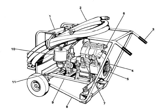
1-1. ORIENTATION VIEWS. The following two illustrations are provided to orient manual user with the overall air
compressor and specific components.
NOTE
The term "compressor" will refer to the overall machine and the term
"pump" will refer to the rotary vane air pump acting as a blower.
NOTE
The terms "left" and "right" will refer to sides of the machine as viewed
by the operator while standing behind the machine at the hand grips.
1. TOOL BOX
2. AIR HOSES
3. HAND GRIPS
4. GAS ENGINE
5. ROPE STARTER
6. ON/OFF SWITCH
7. OIL FILL & DIPSTICK
8. FRAME
9. ENGINE/PUMP SUPPORT
10. AIR FILTER
11. AIR PUMP
Air Compressor, Left Side View
1-1

