TM 5-4310-381-13
SECTION III. TECHNICAL PRINCIPLES OF OPERATION
1-13. OPERATION OF THE AIR COMPRESSOR.
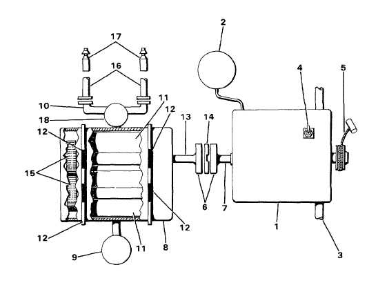
1.
GAS ENGINE
10. OUTLET TEE
2.
FUEL TANK
11. IMPELLERS
3.
ENGINE AIR FILTER
12. BEARINGS
4.
ON/OFF SWITCH
13. DRIVE SHAFT
5.
ROPE STARTER
14. NEOPRENE INSERT
6.
COUPLING
15. TIMING GEARS
7.
CRANKSHAFT
16. AIR HOSES
8.
AIR PUMP
17. INFLATOR VALVE
9.
PUMP AIR FILTER
18. SAFETY VALVE
Compressor Operation
a. Gas Engine (1). Draws gas from the frame-mounted tank (2) and air through its own air filter (3). Controlled by an
ON/OFF switch (4) and started by a pull rope starter (5). Through use of piston, connecting rods, and crankshaft,
produces 3 hp. Connected to the air pump through a coupling (6) mounted on engine crankshaft (7).
b
Air Pump (8). Rotary impellers compress air taken in through the pump air filter (9) and forces air out through the
outlet tee (10). Impellers (11 ) are mounted on shafts of unequal length and supported by bearings (12) on both ends.
Longer shaft serves as the drive shaft (13) and is connected to the engine through coupling (6) and a neoprene insert
(14). Impellers are held in proper time by timing gears (15) mounted on opposite ends of drive shafts.
c. Safety Valve (18). A safety valve with relief setting of 6.5 psi prevents pressure buildup in the air pump and hoses.
d. Air Hoses (16). Two 25 ft. hoses are stored on the frame for transport. Quickly connected to outlet tee (10) to
provide air to the inflator valve assemblies (17). Assemblies are specially designed for inflating ponton floats.
1-6


