
8 Crankshaft
KEY to Figure 3-1
KEY to Figure 3-1
9 Ring
1 Screw
11 Rod assembly
1 Cylinder
10 Gasket
2 End plate
12 Bearing, sleeve
2 Gasket
11 End plate
13 Pin, piston
3 Shim
3 Ring
12 Screw
4 Cup. bearing
14 Piston, high pressure
4 Ring
13 Baffle. side
.5 Gasket
5 Piston. low pressure
15 Ring
14 Baffle. center
6 Pin. cotter
16 Ring
13 Pin, cotter
7 Bearing
17 Screw
7 Screw
8 Lockwasher
18 Pin. piston
19 Pin. cotter
9 Bearing, half
20 Bearing, sleeve
10 Rod assembly
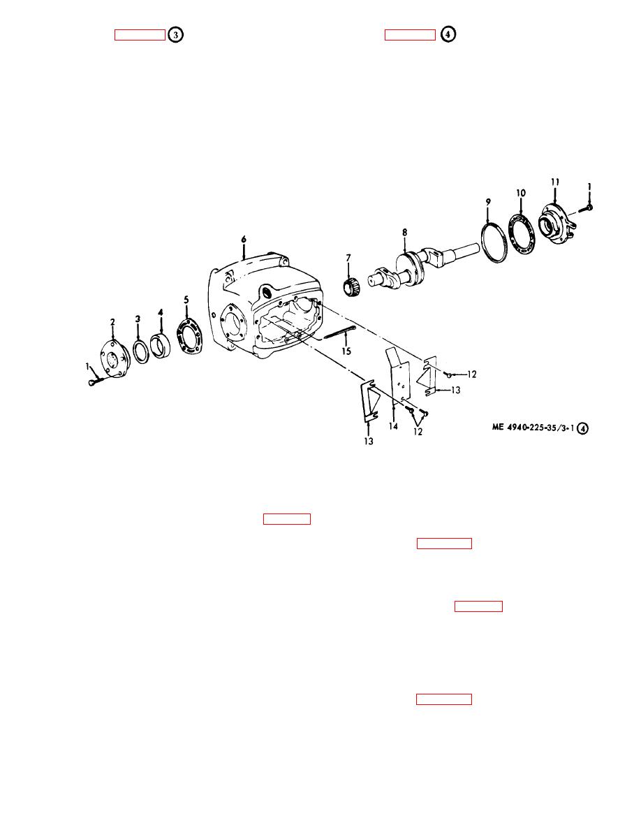
Figure 3-1. Air compressor, disassembly and reassembly (sheet 4 of 4).
( 8 ) Replace all unserviceable parts as
d. Cleaning, Inspection and Repair.
necessary. Weld minor breaks and cracks.
(1) Clean all parts with approved cleaning
e. Reassembly.
solvent and dry thoroughly. Refer to table 1-1 for
tolerances.
(1) Reassemble the air compressor as
illustrated in figure 3-1.
(2) Inspect the intercooler for cracks, breaks,
and dam aged fins.
(2) Use a piston ring compressor to install the
pistons in the cylinder head.
(3) Inspect the cylinders and crankshaft
bearings for cracks, breaks, scoring, wear, warpage,
(3) The crankshaft bearing adjustment is
made by removing or adding shims at the small
and other damage or defects.
crankcase end plate (table 1-1 ).
(4) Inspect the cylinder head for cracks,
breaks, warpage, and other damage.
f. Installation. Install the air compressor (TM
5-4940-225-12).
(5) Inspect the valve plate and valves for wear
and defects.
3-2. Air Compressor Drive Motor
(6) Inspect the crankcase for cracks, breaks,
a. Removal. Remove the drive motor (TM 5-
and damaged threads.
4940-225-12).
(7) Inspect the pistons, rings, and pins for
b. Disassembly. Disassemble the drive motor as
dam age and defects.
illustrated in figure 3-2.
3-5
