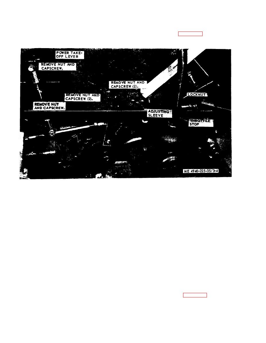
3-6. Overspeed Linkage (Model SEORL Only)
The overspeed linkage which prevents engine
overspeed after the power take-off lever is engaged,
a. G e n e r a l . T h e t r u c k e n g i n e p r o v i d e s
is accessible by removing the truck cab center
mechanical power for driving the dynamotor-
floorboard.
welder, and the operating speed is 1000 or 1200
rpm to furnish 50 or 60 cycle alternating current.
overspeed linkage.
Figure 3-4. Overspeed linkage. removal and installation. (Model SEORL Only/
3-7. Overspeed Safety Switch (Model SEORLT
c. Adjustment.
Only)
(1) Start engine and engage power take-off
(TM 5-4940-225-121.
a. On-Equipment Testing.
(2) With transmission in fifth gear position.
(1) Tag and disconnect all electrical leads at
slowly depress accelerator until accelerator linkage
the resistor and the solenoid coil lead at the ter-
makes contact with throttle stop.
minal strip.
(3) At full throttle tachometer reading should
12) Use a multimeter and test the resistor for
he 1200 rpm for 60 cycle and 1000 rpm for 50
smooth increments in resistance from 0 to 1,000
cycle electricity y.
ohms. Replace a defective resistor.
(4) To adjust engine speed, loosen locknut
(3) Use a multimeter to measure the
and turn throttle stop in or out of adjusting sleeve.
resistance of the 300 ohm coil. If the variance is
Turn throttle stop clockwise to increase speed and
greater than plus or minus 2 percent, replace the
counterclockwise to decrease speed.
coil.
(5) After proper engine speed is obtained,
(4) Connect a multimeter to circuits 115 and
tighten locknut against adjusting sleeve.
116: continuity should not be indicated. Activate
the overspeed switch by hand: if continuity is not
Note. If further adjustment is required. loosen the
indicated, replace the microswitch.
locknuts on both ends of the adjusting sleeve and change
(5) Connect previously tagged leads as
position of the sleeve as required.
necessary.
d. Installation. Install in reverse order of
the overspeed safety switch assembly.
b above.
3-8


