
removable bracket secured to the shop set floor.
3-36. Doors and Hinges
Hydraulic oil flows into and out of the cylinders
a. General. The side and rear doors should not
through a flexible line connected at the bottom of
be removed unless absolutely necessary. In most
each cylinder.
cases, repairs can be made with the doors installed.
b. Removal. Remove the side lifting cylinder
b. Removal. Support the door to prevent
(TM 5-4940-22.5-12).
damage prior to removing hardware. Remove
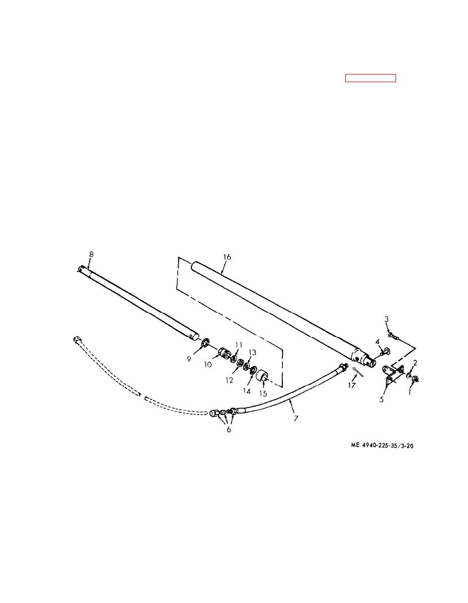
c. Disassembly. Refer to figure 3 - 2 0 and
mounting hardware.
disassemble the side lifting cylinder.
c. Cleaning, Inspection, and Repair.
d. Cleaning, Inspection, and Repair.
(1) Clean doors with approved cleaning
(1) Clean all parts with an approved cleaning
solvent and dry thoroughly.
solvent and dry thoroughly.
(2) Inspect doors for cracks. breaks. dents.
(2) Inspect all parts for cracks, breaks, wear
rust, and other damage or defects.
and other defects. Inspect the interior surface of the
(3) Break rivets if necessary to make repairs,
cylinder for pits, roughness, and scored condition.
straighten bends, weld cracks and breaks. Replace
(3) Install new packing kit, which includes
defective hinges.
the wiper, O-rings, and backup washers.
d. Installation. Install in reverse of b above.
(4) Replace a damaged or defective side
3-37. Side Lifting Cylinder and Hydraulic
lifting cylinder or related parts.
Lines
e. Reassembly and Installation.
a. General. A side lifting cylinder is located on
(1) Reassemble in reverse order of c, above.
each side of the shop set body. The upper end of
(2) Install the side lifting cylinder (TM 5-
each cylinder is attached to a rib in its respective
4940-225-12).
side door. The lower end of each is connected to a
1 Nut
10 Gland
2 Washer
11 Washer
3 Screw
12 O-Ring
4 l'in
13 Washer
5 Bracket
14 O-Ring
6 Connector
15 Piston
7 Hose assembly
16 Butt and tube assembly
8 Rod
17 Pin
9 Wiper
Figure 3-20. Side lifting cylinder. disassembly and reassembly.
3-28
