TM 55-4920-215-15
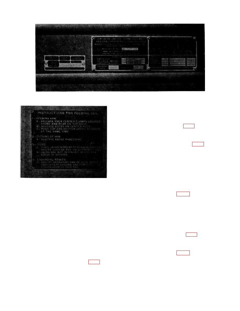
Figure 2. Identification pates, shop set, C-6.
Safety devices ............ Safety disconnect switch.
Controls ...................... Thermal-magnetic circuit
breaker panel; 14 break-
era (fig. 4).
Electrical
connections,
equipment ................... Receptacles and circuit
breakers (fig. 4).
(2) Pneumatic system
Power source .............. External; compressor or
storage tank.
Pneumatic power
requirements ............. 5 cfm at 175 psi working
pressure
Pneumatic
Figure 3. Instruction plate, shop set, C-6.
connections,
shop.......................... Quick disconnect fittings
Generator mount- Skid type.
Pneumatic
ing.
connections,
Generator rating ........... Single and three-phase, 10
equipment ................ Quick disconnect fittings;
kw, 208 v, ac, line-to-
air hose and adapters
line, 120 v, line-to-neutral
Safety devices ............. Safety relief valve.
or line-to-line, three-
Controls ....................... Shutoff valve; oil and water
phase, 60 cycle operation;
separator, gages, regula-
or 10 kw, 120-240 v, line-
tors, valves, and check
to-line, single phase, 60
units (fig. 5).
cycle operation.
Pneumatic
Electrical
connections,
connections,
equipment ................ -Quick disconnect fittings
shop ......................... Power cable, male to female
joy plug for shop or pot
(3) Utility System
head assembly for auxil-
Type equipment .......... Bench tops maple, size A;
iary operation (fig. 8).
storage cabinet, Type I
and III.
6


