
TM 9-4933-223-13&P
NOTE
NOTE
Step 3 is performed only
Steps 4 thru 7 list parts which
once at the time of initial
form airhose connections on
installation.
the inside and outside of the
3
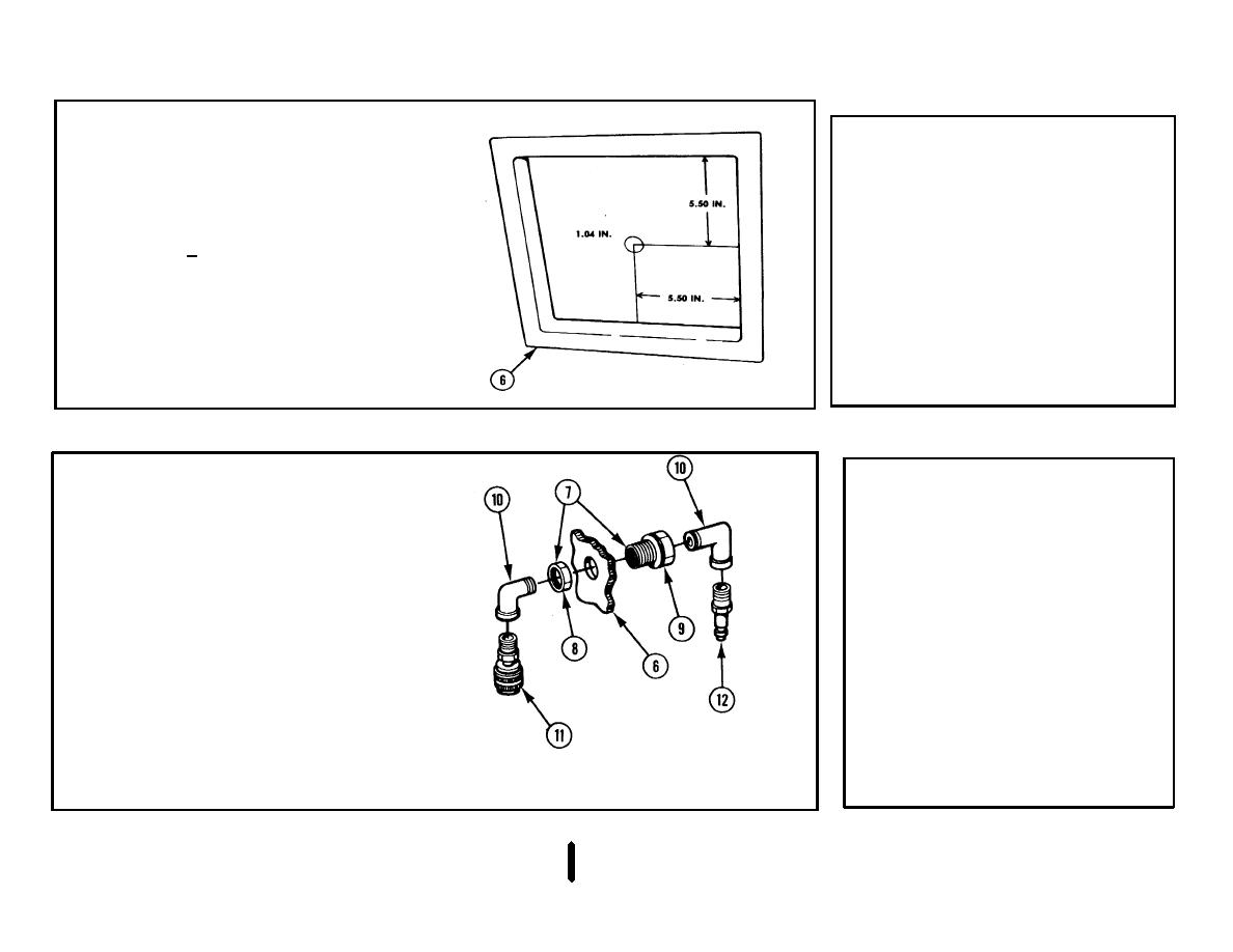
SHELTER PAN (6). Drill a 1.04- in.
shelter wall to left of
(2.64-cm) +0.01-in. (0.03-cm) diameter
personnel door (viewed from
hole through, 5.50 in. (13.97 cm) to left
outside).
of right edge and 5.50 in. (13.97 cm)
down from top edge (viewed from
outside).
4
BULKHEAD ADAPTER (7)
NOTE
a. Remove nut (8) from body (9).
All airhoses may now be
b. Install body (9) through shelter pan
connected to the coupling
(6) adjacent to personnel door.
assemblies.
c.
Tighten nut (8) on body (9).
Steps 8 thru 11 list parts used
to
secure
the
portable
5
TWO ELBOWS (10). Install on two
degreaser
and
storage
ends of bulkhead adapter (7).
cabinet to the shelter floor.
6
FEMALE COUPLING ASSEMBLY (11).
Install on inside of shelter.
7
MALE COUPLING ASSEMBLY (12).
Install on outside of shelter.
3-35
