
TM 9-4933-223-13&P
4
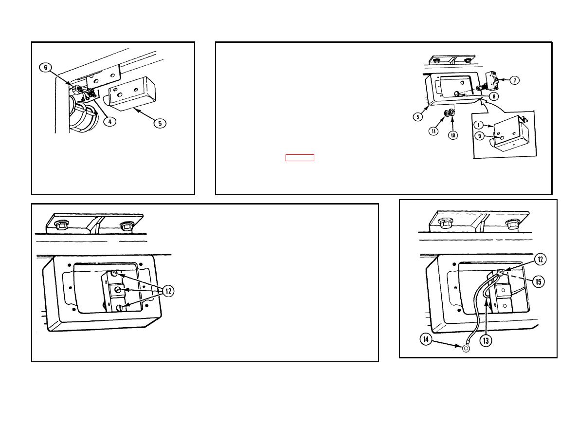
MICROSWITCH (7). Install in hole (8) in
back of switchbox (5) and through hole
(9) in mounting bracket (1).
NOTE
Adjust microswitch so that
plunger protrudes enough so
when door bolt is closed the
plunger is depressed, and when
door bolt is open the plunger is
released.
For
further
2
HARNESS ASSEMBLY (4). Push into
instructions, refer to adjustment
switchbox (5).
of microswitch, p 3-178.
3
CONNECTOR (6). Install in switchbox
5
WASHER (10) AND HEX NUT (11).
(5).
Install.
NOTE
Black wire no. 8 and black wire
no. 4B will be installed when
connected.
7
BLACK WIRE NO. 4A (13) AND BLACK
WIRE NO. 4B (14).
a. Connect to terminal no. NC (15).
b. Reinstall terminal screw (12).
6
THREE TERMINAL SCREWS (12).
Remove.
3-175
