
TM 9-4933-223-13&P
13-39. 120/208V CABLE ASSEMBLY--MAINTENANCE INSTRUCTIONS (cont)
REASSEMBLY (cont)
NOTE
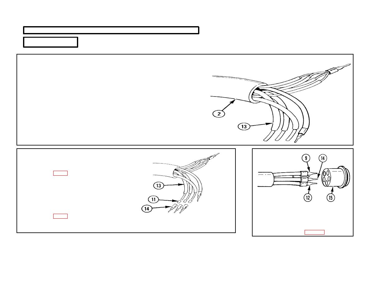
Step 12 pertains to three wires which are black, red, and blue or orange in
color.
12
THREE WIRES (13).
a.
Cut carefully to allow wires to protrude 3.25 in. (8.26 cm) from
outer jacket (2).
b.
Remove 0.75 in. (1.91 cm) of insulation from end of wires.
c.
Twist ends.
13
THREE BUSHINGS (11).
a.
Slip onto three wires (13).
b.
Solder in place using solder (item
16, app D).
14
THREE CONTACT PINS (A, B,
AND C) (14).
a.
Slip on three bushings (11)
attached to three wires (13).
15
CONTACT PIN (G) (9), CONTACT
b.
Solder in place using solder (item
PIN (N) (12), AND THREE
16, app D).
CONTACT PINS (A, B, AND C) (14).
Install in pin socket (15) according to
information in table 3-8.
3-288
