
TM 9-4933-223-13&P
3-41. 120/208V CABLE ASSEMBLY--ELECTRICAL PLUG CONNECTOR (MALE)--MAINTENANCE INSTRUCTIONS
THIS TASK COVERS:
a.
Removal
d. Repair
b.
Inspection
e. Installation
c.
Service
INITAL SETUP
Contact pin (N) (M39029/48-321)
Preformed packing (MS29513-132)
Special Tools
Armament repair shop set (SC 4933-95-CL-A2
References
Basic aircraft armament repair tool set
(SC 5180-95-CL-B09)
Reassembly, test, and installation procedures for
Removal tool no. 4 (MS90562-5)
120/208V cable assembly.
Removal tool no. 6 (MS90562-6)
Removal and disassembly procedures for 120/208V
Supplemental aircraft armament repair tool set
cable assembly.
(SC 5180-95-CL-B10)
Material s/Parts
Troubleshooting Reference
Polishing cloth (item 5, app D)
Environmental control units or exhaust fans do not operate
Solder item 5 Tem 16, app D)
correctly.
Contact pin (A, B, and C) (3) (M39029/48-320)
Contact pin (G) (M39029/48-318)
REMOVAL
INSPECTION
Refer to removal and disassembly procedures on paragraph 3-39, page 3-
1
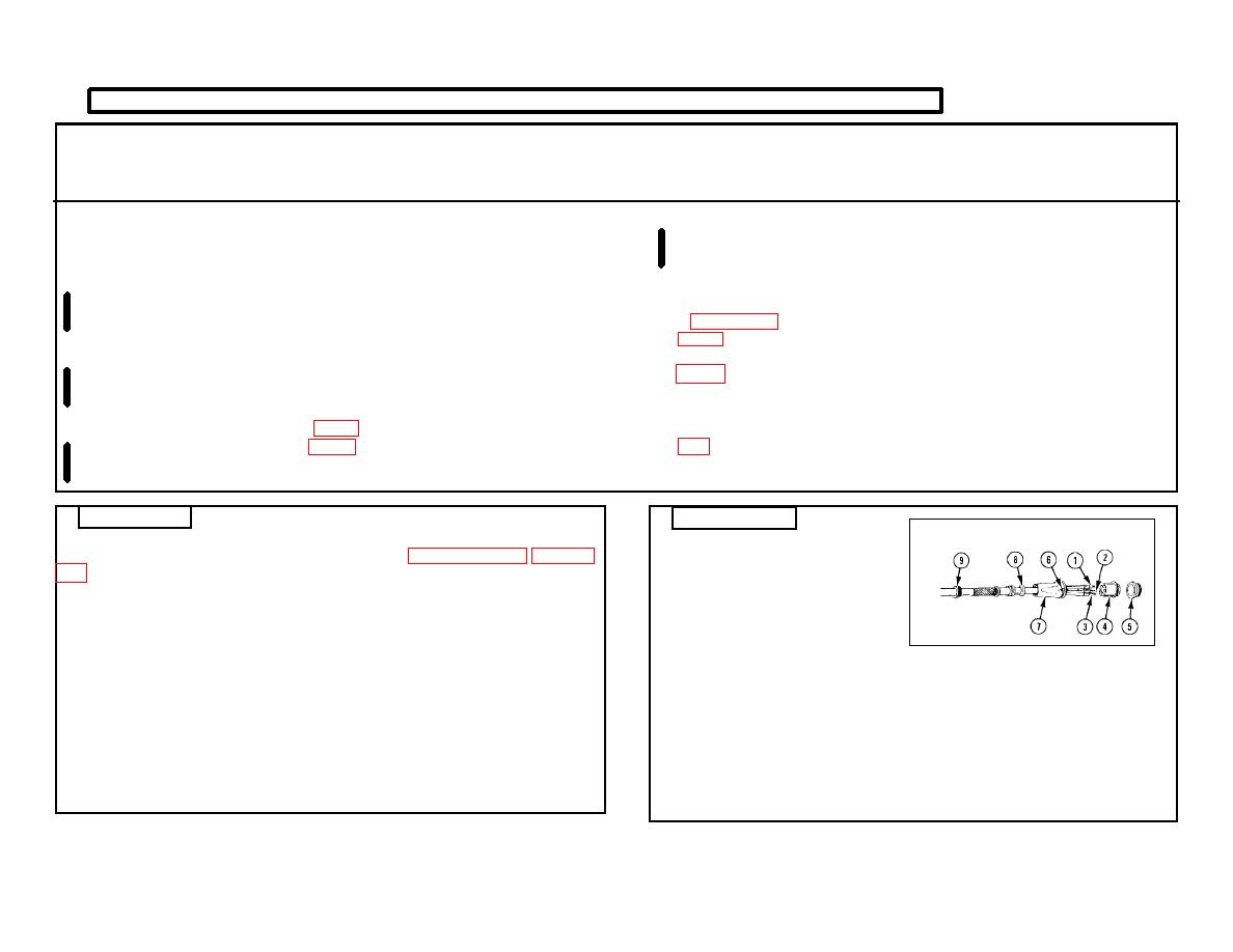
CONTACT PIN (G) (1),
CONTACT PIN (N) (2), AND
THREE CONTACT PINS (A,
B, AND C) (3). Check for
bent, broken, or corroded
parts.
2
PIN SOCKET (4), FORWARD
CONNECTOR HOUSING (5),
THREE SCREWS (6), REAR
CONNECTOR HOUSING (7),
SPACER (8), AND GLAND
NUT (9). Check for bent or
broken parts.
Change 1 3-298
