
TM 9-4940-549-14&P
MAINTENANCE OF CONTROL CUBICLE
ROTARY SWITCH (10-RANGE).
a.
Removal.
(1) Remove four screws and remove welder control panel.
(2) Tag and disconnect electrical leads as necessary.
(3) Remove four screws and lockwashers and remove rotary switch.
b.
Disassembly.
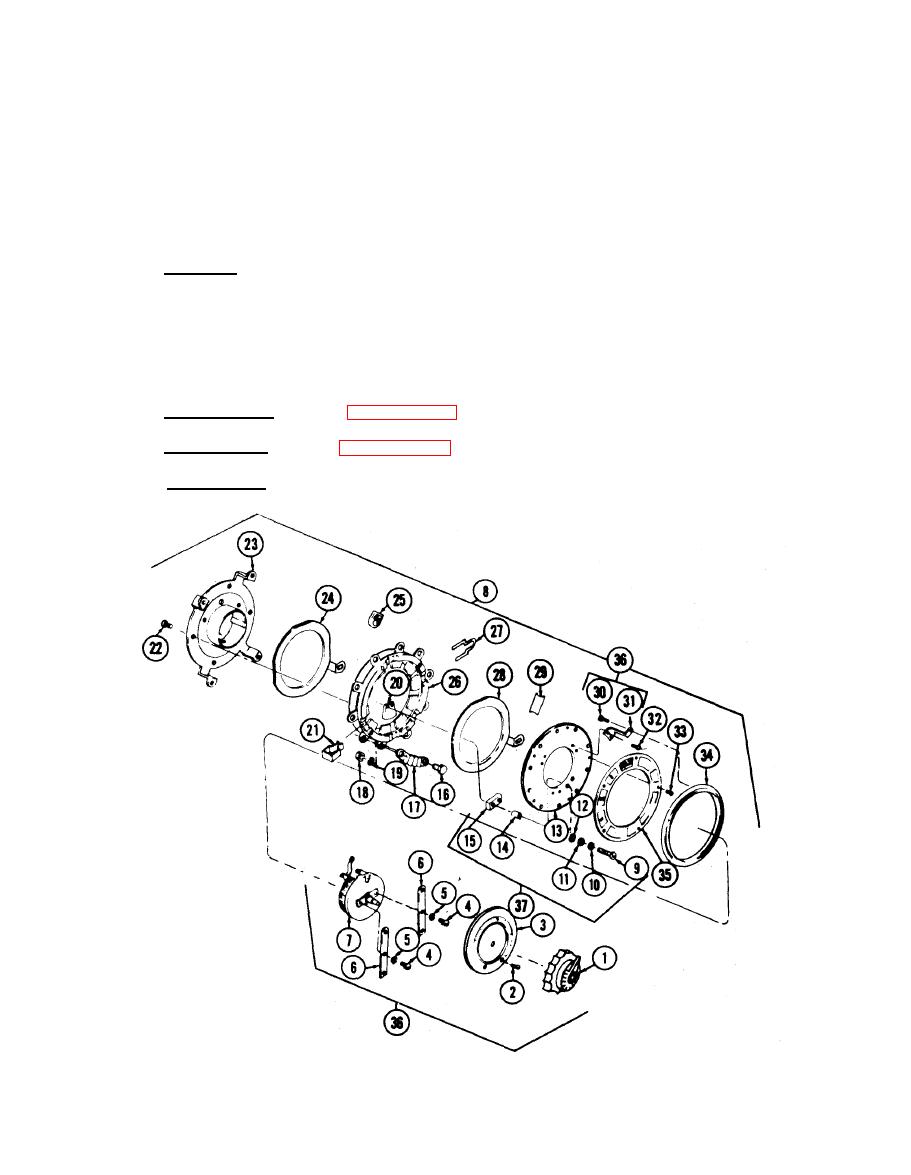
Refer to figure 18-1, and disassemble rotary switch.
Refer to figure 18-1. and reassemble rotary switch.
c.
Reassembly.
Install in reverse order of subparagraph 18-la.
Installation.
d.
Rotary Switch (lO-Range), Exploded View.
