
0002 00
TM 1-4920-433-13&P
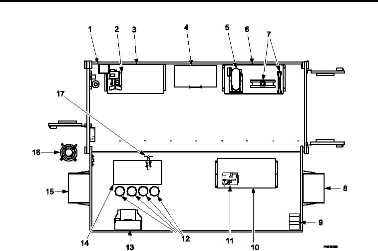
LOCATION AND DESCRIPTION OF MAJOR COMPONENTS CONTINUED
Item No. and Name
Item No. and Name
1. First Aid Kit and Bracket Assembly
10. Shelf Cabinet (G)
2. Portable Hose Assembly Machine
11. Hydraulic Hose Tester Assembly
3. Three Drawer Cabinet (A) and Six Drawer
12. Straight Stools (4)
Cabinet (B)
4. Degreaser Machine
13. Eyewash Station Assembly
5. Upright Drilling Machine
14. Four Drawer Cabinet (E) and Four Drawer (F)
15. ECU (A)
6. Four Drawer Cabinet (C) and Four Drawer
Cabinet (D)
7.10 Ton Hydraulic Press
16. Cable Reel Assembly and 60 amp Power
Cable Assembly
17. Machinist s Vise
8. ECU (B)
9. Case Set
Figure 6.
Operational Mode Component View (1036258).
0002 00-6