
TM 1-4920-433-13&P
0005 00
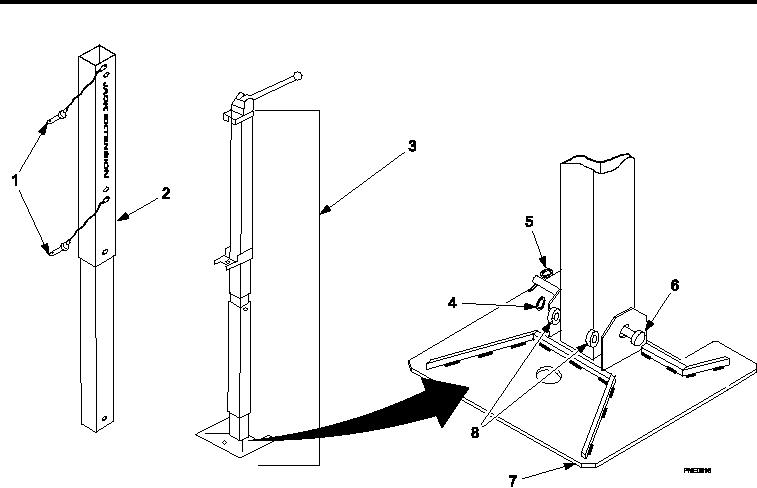
POSITIONING HINGED JACK ASSEMBLIES FOR LEVELING CONTINUED
Figure 9.
Hinged Jack Assemblies Extensions.
4.
Install jack extensions (Figure 9, Item 2) (if necessary).
a.
Remove two jack extensions (Figure 9, Item 2) from Shelter BII box .
b.
Remove one cotter pin (Figure 9, Item 5) from shaft (Figure 9, Item 6) of jack assembly base (Figure 9,
Item 7).
c.
Remove shaft (Figure 9, Item 6), two bushings (Figure 9, Item 8), and one lat washer (Figure 9, Item 4).
d.
Position jack extension (Figure 9, Item 2) in jack base (Figure 9, Item 7) and secure by installing shaft
(Figure 9, Item 6) through two bushings (Figure 9, Item 8).
e.
Install one lat washer (Figure 9, Item 4) on end of shaft (Figure 9, Item 6) and install one cotter pin
(Figure 9, Item 5).
f.
Position hinged jack assembly (Figure 9, Item 3) on jack extension (Figure 9, Item 2) and secure by
installing one quick-disconnect pin (Figure 9, Item 1) through upper holes of jack extension (Figure 9,
Item 2) and lower holes of hinged jack assembly (Figure 9, Item 3).
g.
Adjust needed height of jack extension (Figure 9, Item 2) and install one quick-disconnect pin (Figure 9,
Item 1).
0005 00-9