
0005 00
TM 1-4920-433-13&P
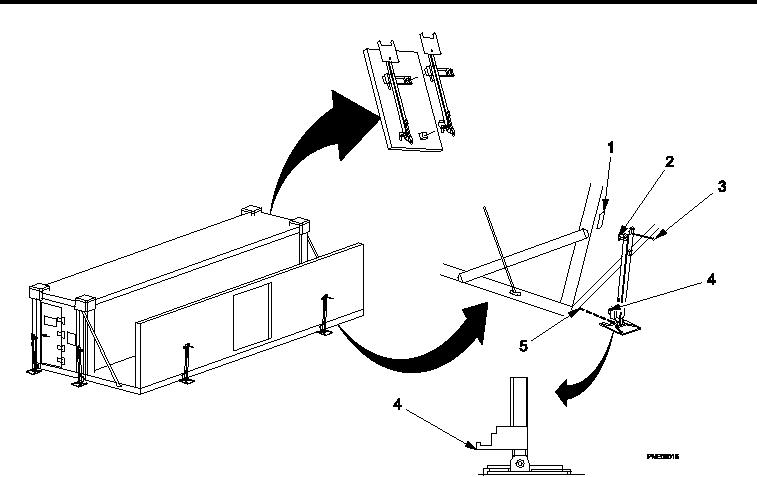
POSITIONING HINGED JACK ASSEMBLIES FOR LEVELING
Figure 8.
Hinged Jack Assemblies.
1.
Remove two hinged jack assemblies from inside of left cargo door.
2.
Position hinged jack assemblies at each corner of expanded side.
NOTE
If Step 3 cannot be successfully completed, perform Step 4 and then return to Step 3.
When Step 3 is successfully completed, go to Step 5.
Stencil on hinged jack assemblies indicates handle rotation to raise or lower jack.
3.
Rotate handle (Figure 8, Item 3) to raise hinged jack assembly until jack lift pin (Figure 8, Item 4) engages in
hinged loor socket (Figure 8, Item 5) and upper jack hook (Figure 8, Item 2) engages in jack support bracket
(Figure 8, Item 1) on hinged sidewall.
0005 00-8