
0020 00
TM 1-4920-433-13&P
POSITIONING ECU (A) FOR TRANSPORT MODE
1.
Remove four setscrews from ECU (A) transport location loor inserts and store in cotton mailing bag located
in shelter BII box .
2.
Remove two cargo straps (Figure 5, Item 3) from secure storage location and four ring bolts (Figure 5, Item
4) from shelter BII box .
3.
Install four ring bolts (Figure 5, Item 4) into loor inserts at transport location.
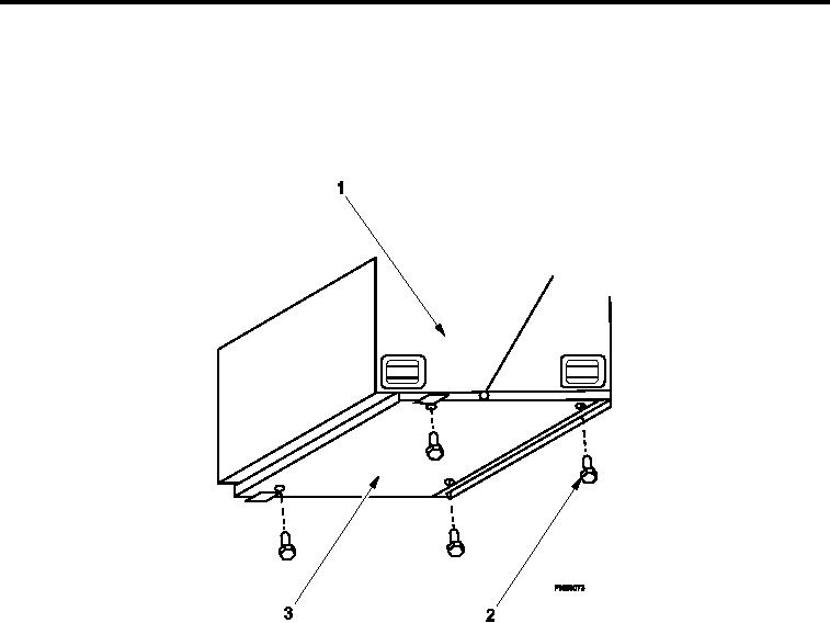
Figure 4.
Removing ECU (A) Hardware from ECU Fold-down Panel.
4.
Remove mounting hardware securing ECU (A) (Figure 4, Item 1) to ECU fold-down panel (Figure 4, Item 3).
5.
Store hardware in cotton mailing bag located in shelter BII box .
0020 00-4