
0039 00
TM 1-4920-433-13&P
INSPECTION OF INSTALLED ITEMS
HOSE ASSEMBLY MACHINE MOUNTING HARDWARE
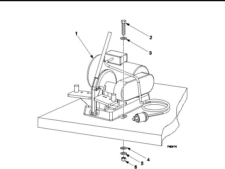
Figure 4.
Hose Assembly Machine.
1.
Inspect hose assembly machine (Figure 4) for damage. Replace as necessary.
2.
Inspect hose assembly machine hardware (Figure 4, Item 2 through 6) for rust, cracks and rounded heads.
Replace as necessary.
REMOVAL
Remove three bolts (Figure 4, Item 2), three upper lat washers (Figure 4, Item 3), three lower lat washers (Figure
4, Item 4), three lock washers (Figure 4, Item 5), and three nuts (Figure 4, Item 6).
INSTALLATION
Replace hose assembly machine (Figure 4, Item 1) by installing three bolts (Figure 4, Item 2), three upper lat
washers (Figure 4, Item 3), three lower lat washers (Figure 4, Item 4), three lock washers (Figure 4, Item 5), and
three nuts (Figure 4, Item 6).
END OF WORK PACKAGE
0039 00-4