
TM 1-4920-433-13&P
FIELD MAINTENANCE
PNEUDRAULIC SHOP
MAINTENANCE INSTRUCTIONS FOR 240V OUTLET BOX ASSEMBLY AND COVER
INITIAL SETUP:
Personnel Required
Tools and Special Tools
CMF 15 Series (1)
Electrical Repairers Tool Kit
Equipment Condition
(WP 0062 00, Table 2, Item 103 )
Functional
Multimeter (WP 0062 00, Table 2, Item 106 )
WARNING
HIGH VOLTAGE exists in electrical system of shop. All electrical inspections, repairs, or
replacements will be performed with power OFF and only by a qualiied electrician. Serious
shock hazards exist which could result in INJURY OR EVEN DEATH to personnel.
NOTE
During installation of components same hardware should be used so as to maintain original
integrity of shop set.
INSPECTION OF INSTALLED ITEMS
240V OUTLET BOX ASSEMBLY
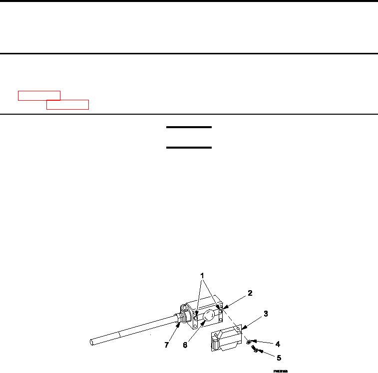
Figure 1.
240V Outlet Box.
1.
Move main circuit breaker to OFF position.
2.
Inspect 240V outlet box assembly (Figure 1, Item 2) and cover (Figure 1, Item 3) for damage.
3.
Replace 240V outlet box assembly (Figure 1, Item 2) and/or cover (Figure 1, Item 3) if damage is detected.
0041 00-1