
0041 00
TM 1-4920-433-13&P
INSTALLATION CONTINUED
2.
Slide new box connector onto conduit.
3.
Tighten box connector until it compresses onto conduit securely.
4.
Push wire back to 240V receptacle and reconnect wires.
5.
Move main circuit breaker to ON position.
INSPECTION OF INSTALLED ITEMS
RETAINING STRAP
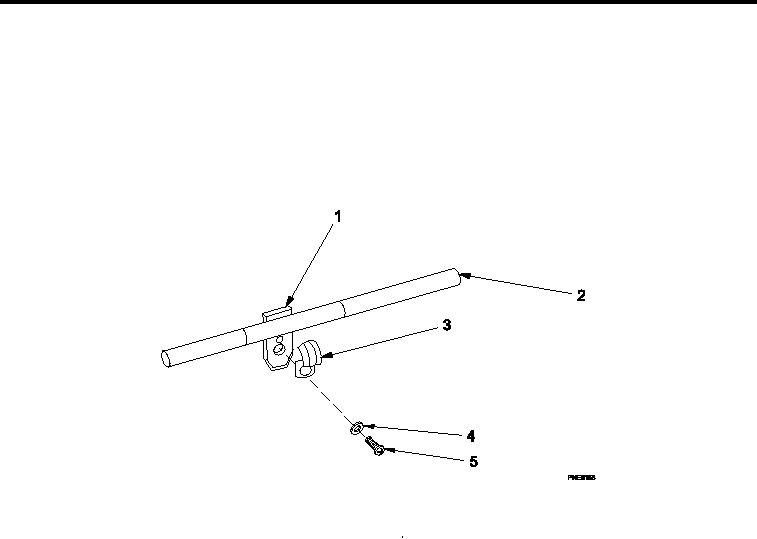
Figure 3.
Retaining Strap.
Inspect retaining strap (Figure 3, Item 3) and spacer (Figure 3, Item 1) for damage.
REMOVAL
1.
Remove machine screw (Figure 3, Item 5) and lat washer (Figure 3, Item 4).
2.
Remove retaining strap (Figure 3, Item 3) and spacer (Figure 3, Item 1).
INSTALLATION
1.
Place new retaining strap (Figure 3, Item 3) and spacer (Figure 3, Item 1) onto conduit (Figure 3, Item 2).
2.
Ensure conduit (Figure 3, Item 2) is properly seated.
3.
Install machine screw (Figure 3, Item 5) and lat washer (Figure 3, Item 4).
END OF WORK PACKAGE
0041 00-4