
TM 1-4920-433-13&P
0051 00
INSTALLATION CONTINUED
DOOR LOCK TABS CONTINUED
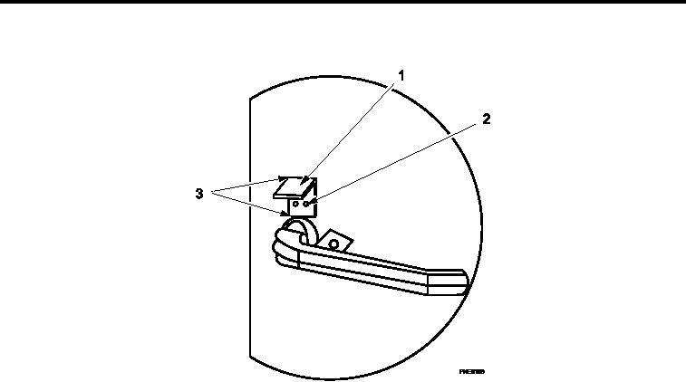
Figure 3.
Door Lock Tabs Installation.
6.
Pull rivets (Figure 3, Item 2) to secure door lock tabs (Figure 3, Item 1) to door.
7.
Weld door lock tabs (Figure 3, Item 1) to door in two places IAW TM 1-1500-204-23.
8.
Apply a bead of polysulide sealant along remaining two sides (Figure 3, Item 3) of door lock tabs (Figure 3,
Item 1) as well as coating rivet heads (Figure 3, Item 2) with polysulide sealant.
9.
Prime and paint IAW TM 43-0139.
END OF WORK PACKAGE
0051 00-3/4 blank