
0052 00
TM 1-4920-433-13&P
INSPECTION OF INSTALLED ITEMS
AIR FEED-THRU CONNECTOR ASSEMBLY
Figure 7.
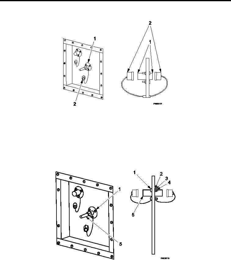
Inspect Air Feed-thru Connector Assembly.
1.
Inspect condition of threads on both ends of air feed-thru connector assembly (Figure 7, Item 1). Replace as
necessary.
2.
Ensure that protective dust caps (Figure 7, Item 2) are attached.
3.
Ensure weld on connector (Figure 7, Item 1) is not cracked or broken. Replace if defective.
REMOVAL
AIR FEED-THRU CONNECTOR ASSEMBLY
Figure 8.
Disassembly of Air Feed-thru Connector Assembly.
1.
Have assistant hold nut (Figure 8, Item 4) and washer (Figure 8, Item 3) inside shelter.
2.
Remove nuts (Figure 8, Item 4), lat washers (Figure 8, Item 2), lock washers (Figure 8, Item 3), and screws
(Figure 8, Item 1), releasing air feed-thru connector assembly (Figure 8, Item 5).
0052 00-6