
TM 1-4920-433-13&P
0052 00
INSPECTION OF INSTALLED ITEMS
COUPLINGS - HYDRAULIC HOSE
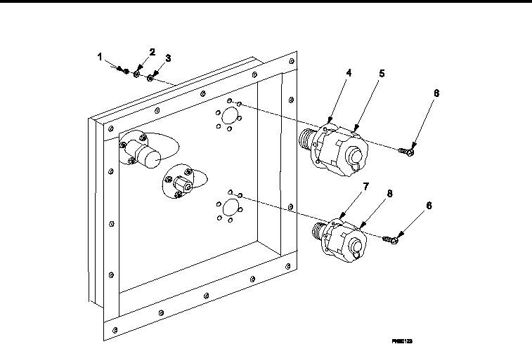
Figure 13.
Inlet Hose Coupling and Return Hose Coupling.
1.
Inspect condition of threads on both ends of inlet hose coupling (Figure 13, Item 4). Replace as necessary.
2.
Ensure that inlet hose coupling protective dust cap (Figure 13, Item 5) is attached.
3.
Inspect condition of threads on both ends of return hose coupling (Figure 13, Item 7). Replace as necessary.
4.
Ensure that return hose coupling protective dust cap (Figure 13, Item 8) is attached.
REMOVAL
1.
Remove six nuts (Figure 13, Item 1), six lat washers (Figure 13, Item 2), six lock washers (Figure 13, Item 3
), and six screws (Figure 13, Item 6), releasing inlet hose coupling (Figure 13, Item 4).
2.
Remove inlet hose coupling (Figure 13, Item 4) from services utility panel.
3.
Remove old caulking compound by scraping with utility knife.
4.
Repeat Steps 1 through 3 for return hose coupling (Figure 13, Item 7).
INSTALLATION
1.
Apply caulking compound on backside of inlet hose coupling (Figure 13, Item 4) lange.
2.
Install new inlet hose coupling (Figure 13, Item 4) from outside of shelter with long end through hole.
3.
Install six screws (Figure 13, Item 6), six lock washers (Figure 13, Item 3), six lat washers (Figure 13, Item
2), and six nuts (Figure 13, Item 1) attaching inlet hose coupling (Figure 13, Item 4).
4.
Repeat Steps 1 through 3 for return hose coupling Figure 13, Item 7).
END OF WORK PACKAGE
0052 00-9/10 blank