
0043 00
TM 1-4920-435-13&P
INSPECTION OF INSTALLED ITEMS
CABINETS (D), (E), AND (F) HARDWARE
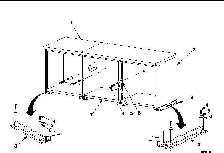
Figure 3.
Cabinets (D), (E), and (F) Hardware.
Inspect cabinet assembly integration hardware (Figure 3) for rust, cracks and rounded heads. Replace as nec-
essary.
REMOVAL
CABINETS (D), (E), AND (F) HARDWARE
1.
Remove kick plate (Kick Plate, INSTALLATION).
2.
Remove drawers, slides, and shelves as necessary (Drawers, Slides, And Shelves, INSTALLATION).
3.
Remove four bolts (Figure 3, Item 4), four lock washers (Figure 3, Item 5), and four lat washers (Figure 3,
Item 6) detaching two cabinet brackets (Figure 3, Item 3) from shelter loor.
4.
Remove three bolts (Figure 3, Item 4), three lock washers (Figure 3, Item 5), and three lat washers (Figure
3, Item 6) detaching cabinet (D) (Figure 3, Item 1), cabinet (E) (Figure 3, Item 7), and cabinet (F) (Figure 3,
Item 2) from shelter wall.
INSTALLATION
CABINETS (D), (E), AND (F) HARDWARE
1.
Install four bolts (Figure 3, Item 4), four lock washers (Figure 3, Item 5), and four lat washers (Figure 3, Item
6) securing two cabinet brackets (Figure 3, Item 3) to shelter loor.
2.
Install three bolts (Figure 3, Item 4), three lock washers (Figure 3, Item 5), and three lat washers (Figure 3,
Item 6) securing cabinet (D) (Figure 3, Item 1), cabinet (E) (Figure 3, Item 7), and cabinet (F) (Figure 3, Item
2) to shelter wall.
0043 00-4